
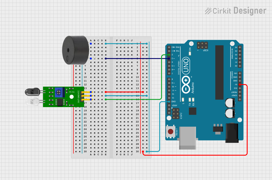
Circuit Documentation
Summary
This circuit is designed to detect obstacles using an FC-51 IR Obstacle Sensor and trigger a buzzer when an obstacle is detected. The circuit is controlled by an Arduino UNO microcontroller.
Component List
Buzzer
- Description: A simple piezoelectric buzzer used to produce sound.
- Pins:
- PIN: Signal input
- GND: Ground
Arduino UNO
- Description: A microcontroller board based on the ATmega328P.
- Pins:
- UNUSED
- IOREF
- Reset
- 3.3V
- 5V
- GND
- Vin
- A0
- A1
- A2
- A3
- A4
- A5
- SCL
- SDA
- AREF
- D13
- D12
- D11
- D10
- D9
- D8
- D7
- D6
- D5
- D4
- D3
- D2
- D1
- D0
FC-51 IR Obstacle Sensor
- Description: An infrared sensor used to detect obstacles.
- Pins:
- Out: Signal output
- GND: Ground
- VCC: Power supply
Wiring Details
Buzzer
- PIN: Connected to D3 on the Arduino UNO
- GND: Connected to GND on the Arduino UNO
Arduino UNO
- D3: Connected to PIN on the Buzzer
- GND: Connected to GND on the Buzzer and GND on the FC-51 IR Obstacle Sensor
- 5V: Connected to VCC on the FC-51 IR Obstacle Sensor
- D2: Connected to Out on the FC-51 IR Obstacle Sensor
FC-51 IR Obstacle Sensor
- Out: Connected to D2 on the Arduino UNO
- GND: Connected to GND on the Arduino UNO
- VCC: Connected to 5V on the Arduino UNO
Code Documentation
// Pin definitions
const int sensorPin = 2;  // Obstacle avoidance module
const int buzzerPin = 3;  // Buzzer

void setup() {
  pinMode(sensorPin, INPUT);   // Set the sensor pin as input
  pinMode(buzzerPin, OUTPUT);  // Set the buzzer pin as output

  // Initialize serial communication for debugging (optional)
  Serial.begin(9600);
}

void loop() {
  // Read the sensor state
  int sensorState = digitalRead(sensorPin);

  if (sensorState == LOW) {  // LOW means obstacle detected for most modules
    digitalWrite(buzzerPin, HIGH); // Turn the buzzer on
    Serial.println("Obstacle detected!"); // Debug message (optional)
  } else {
    digitalWrite(buzzerPin, LOW);  // Turn the buzzer off
    Serial.println("No obstacle."); // Debug message (optional)
  }

  delay(100); // Small delay to avoid rapid switching
}
This code initializes the sensor and buzzer pins, reads the sensor state in the loop, and turns the buzzer on or off based on the sensor state. Debug messages are printed to the serial monitor for optional debugging.