
Arduino UNO Based Air Quality Monitoring System with MQ135 Sensor and Alert Indicators
View and Edit Project In Cirkit Designer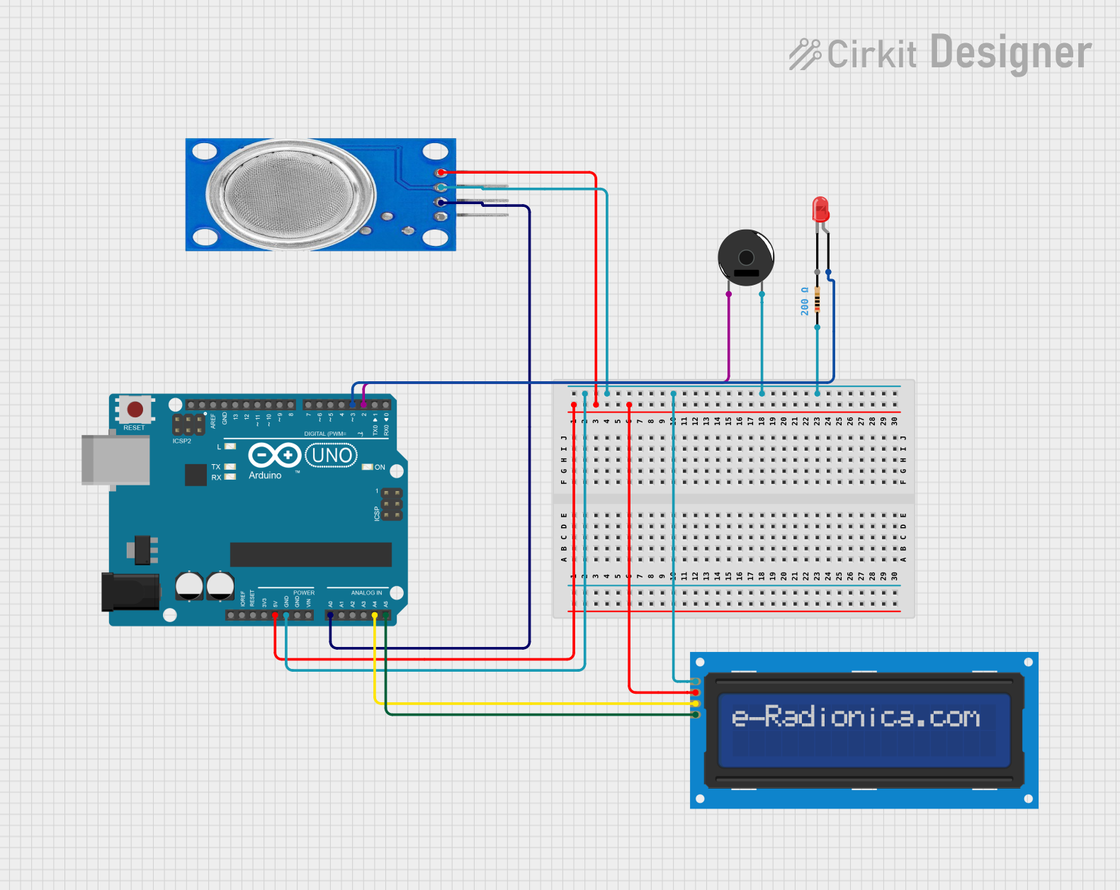
Circuit Documentation
Summary
This circuit is designed to interface with an MQ135 gas sensor, a piezo buzzer, an LED, and an I2C LCD screen using an Arduino UNO microcontroller. The primary function of the circuit is to monitor air quality through the MQ135 sensor and provide visual and audible alerts when the gas concentration exceeds a predefined threshold. The LED serves as a status indicator that remains on at all times, while the buzzer sounds an alarm when the threshold is crossed. The LCD screen displays the sensor readings and provides a user interface for monitoring the sensor's output.
Component List
Arduino UNO
- Microcontroller board based on the ATmega328P
- Provides digital and analog I/O pins
- Includes power supply pins, reset button, and ICSP header
- Utilized for controlling the circuit and processing sensor data
MQ135 Gas Sensor
- Air quality sensor for detecting a wide range of gases, including NH3, NOx, alcohol, benzene, smoke, and CO2
- Provides both analog and digital outputs
Piezo Buzzer
- Electronic device that emits sound when an electric signal is applied
- Used to generate an audible alert
LED: Two Pin (red)
- A simple red light-emitting diode
- Acts as a visual indicator
Resistor
- Passive two-terminal electrical component
- Resistance: 200 Ohms
- Used to limit current to the LED
LCD screen 16x2 I2C
- Alphanumeric liquid crystal display with 16 characters by 2 lines
- I2C communication interface
- Displays sensor readings and messages
Wiring Details
Arduino UNO
5Vconnected to MQ135 VCC and LCD VCCGNDconnected to MQ135 GND, LCD GND, Piezo Buzzer pin 2, and one end of the ResistorA0connected to MQ135 A0 (analog output)A4(SDA) connected to LCD SDAA5(SCL) connected to LCD SCLD2connected to Piezo Buzzer pin 1D3connected to the other end of the Resistor, which is then connected to the anode of the LED
MQ135 Gas Sensor
VCCconnected to Arduino 5VGNDconnected to Arduino GNDA0connected to Arduino A0
Piezo Buzzer
pin 1connected to Arduino D2pin 2connected to Arduino GND
LED: Two Pin (red)
anodeconnected to Arduino D3 through a 200 Ohm Resistorcathodeconnected directly to Arduino GND
Resistor
- One end connected to Arduino D3
- Other end connected to the anode of the LED
LCD screen 16x2 I2C
SCLconnected to Arduino A5SDAconnected to Arduino A4VCCconnected to Arduino 5VGNDconnected to Arduino GND
Documented Code
/*
 * This Arduino sketch interfaces with an MQ135 gas sensor, a piezo buzzer,
 * an LED, and an I2C LCD screen. The code reads the analog value from the
 * MQ135 sensor every 10 seconds. If the sensor value exceeds a threshold
 * of 200, the LED will blink for 3 seconds, and the buzzer will sound for
 * half a second at a high frequency. The LED remains on at all other times.
 */

#include <Wire.h>
#include <LiquidCrystal_I2C.h>

// Pin definitions
const int mq135Pin = A0;
const int buzzerPin = 2;
const int ledPin = 3;

// Threshold value
const int threshold = 200;

// LCD setup
LiquidCrystal_I2C lcd(0x27, 16, 2);

void setup() {
  pinMode(mq135Pin, INPUT);
  pinMode(buzzerPin, OUTPUT);
  pinMode(ledPin, OUTPUT);
  digitalWrite(ledPin, HIGH); // Keep LED on
  lcd.begin();
  lcd.backlight();
  lcd.print("MQ135 Sensor");
}

void loop() {
  int sensorValue = analogRead(mq135Pin);
  lcd.setCursor(0, 1);
  lcd.print("Value: ");
  lcd.print(sensorValue);
  delay(10000); // Wait for 10 seconds

  if (sensorValue > threshold) {
    // Blink LED for 3 seconds
    for (int i = 0; i < 6; i++) {
      digitalWrite(ledPin, LOW);
      delay(250);
      digitalWrite(ledPin, HIGH);
      delay(250);
    }
    // Buzz buzzer for half a second
    tone(buzzerPin, 2000); // High frequency tone
    delay(500);
    noTone(buzzerPin);
  }
}
This code is designed to be uploaded to the Arduino UNO microcontroller. It initializes the connected devices and continuously monitors the MQ135 sensor's analog output. When the gas concentration exceeds the threshold, it activates the LED and buzzer to alert the user. The LCD screen displays the current sensor value for real-time monitoring.