
Arduino UNO RFID Access Control with Visual and Audio Indicators
View and Edit Project In Cirkit Designer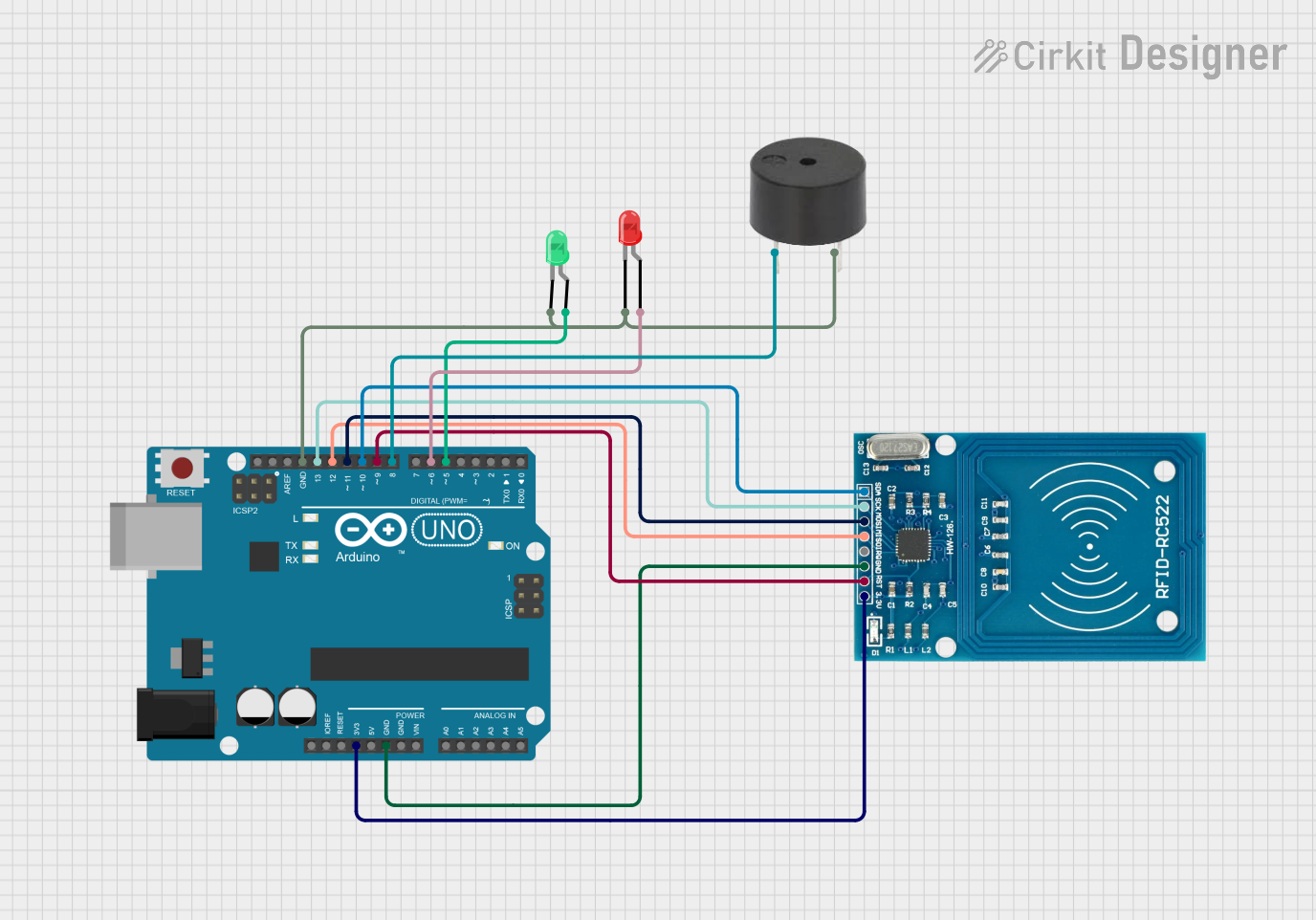
Circuit Documentation
Summary
This document provides a detailed overview of a circuit that includes an Arduino UNO microcontroller, an RFID-RC522 module, a buzzer, and two LEDs (one red and one green). The circuit is designed to interface with the RFID module, provide visual indicators through LEDs, and an audible alert using a buzzer. The Arduino UNO serves as the central processing unit, controlling the RFID reader for tag detection and managing the output signals to the LEDs and buzzer.
Component List
Arduino UNO
- Description: A microcontroller board based on the ATmega328P.
- Purpose: Acts as the central controller for the circuit, interfacing with the RFID module, driving the LEDs, and controlling the buzzer.
RFID-RC522
- Description: An RFID reader/writer module.
- Purpose: To read RFID tags and communicate the data to the Arduino UNO.
Buzzer
- Description: An electromechanical component that produces sound.
- Purpose: To provide an audible alert or feedback.
LED: Two Pin (red)
- Description: A red light-emitting diode.
- Purpose: To serve as a visual indicator, possibly indicating a specific status or condition.
LED: Two Pin (green)
- Description: A green light-emitting diode.
- Purpose: To serve as a visual indicator, possibly indicating a different status or condition than the red LED.
Wiring Details
Arduino UNO
- 3.3V connected to RFID-RC522 VCC (3.3V)
- GND connected to:
- RFID-RC522 GND
- Buzzer GND
- Red LED cathode
- Green LED cathode
- D13 connected to RFID-RC522 SCK
- D12 connected to RFID-RC522 MISO
- D11 connected to RFID-RC522 MOSI
- D10 connected to RFID-RC522 SDA
- D9 connected to RFID-RC522 RST
- D8 connected to Buzzer PIN
- D6 connected to Red LED anode
- D5 connected to Green LED anode
RFID-RC522
- VCC (3.3V) connected to Arduino UNO 3.3V
- RST connected to Arduino UNO D9
- GND connected to Arduino UNO GND
- IRQ (Not connected)
- MISO connected to Arduino UNO D12
- MOSI connected to Arduino UNO D11
- SCK connected to Arduino UNO D13
- SDA connected to Arduino UNO D10
Buzzer
- PIN connected to Arduino UNO D8
- GND connected to Arduino UNO GND
LED: Two Pin (red)
- Anode connected to Arduino UNO D6
- Cathode connected to Arduino UNO GND
LED: Two Pin (green)
- Anode connected to Arduino UNO D5
- Cathode connected to Arduino UNO GND
Documented Code
Arduino UNO Code (sketch.ino)
void setup() {
  // put your setup code here, to run once:

}

void loop() {
  // put your main code here, to run repeatedly:

}
Additional Notes
- The provided code is a template and does not contain any functional code for operating the circuit. The user is expected to implement the setup and loop functions to initialize the RFID module, read tags, and control the LEDs and buzzer based on the RFID tags read.
- The
documentation.txtfile is empty and does not contain any additional information.