
Arduino Nano-Based Stepper Motor Controller with SD Card Logging
View and Edit Project In Cirkit Designer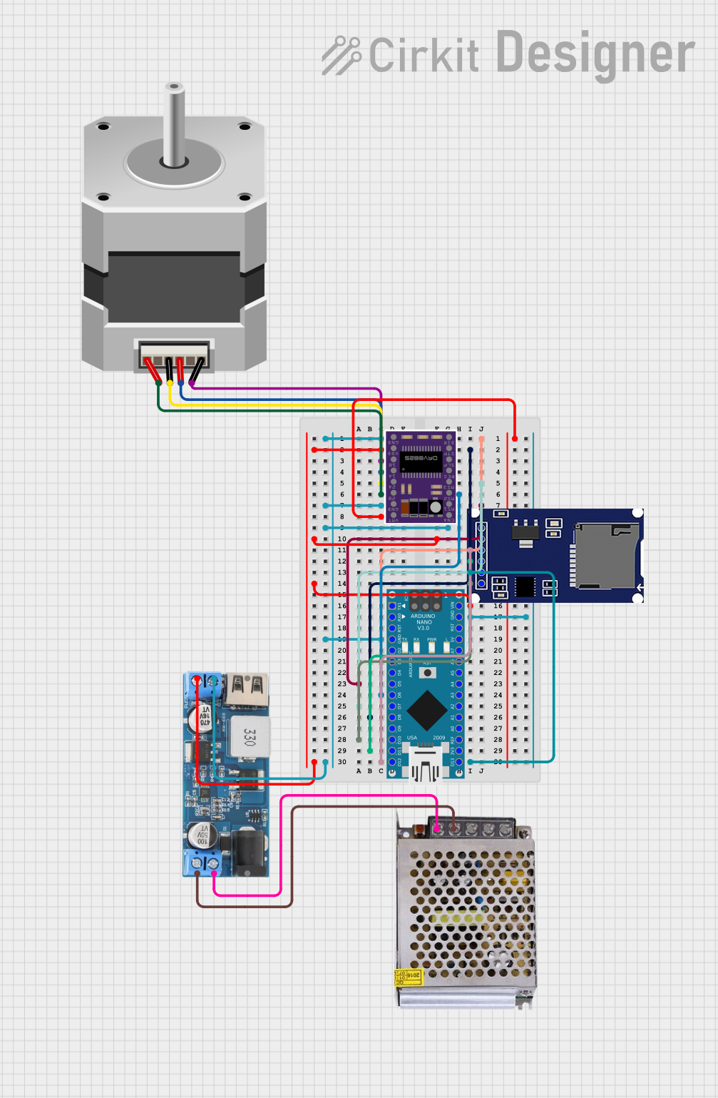
Circuit Documentation
Summary
This document provides a detailed overview of a circuit that includes an Arduino Nano, a DRV8825 stepper motor driver, a bipolar stepper motor, an SD module, a 12V to 5V step-down power converter, and a 12V 5A power supply. The circuit is designed to control a stepper motor and interface with an SD card for data storage.
Component List
Arduino Nano
- Description: A compact microcontroller board based on the ATmega328P.
- Pins: D1/TX, D0/RX, RESET, GND, D2, D3, D4, D5, D6, D7, D8, D9, D10, D11/MOSI, D12/MISO, VIN, 5V, A7, A6, A5, A4, A3, A2, A1, A0, AREF, 3V3, D13/SCK
DRV8825
- Description: A stepper motor driver capable of driving bipolar stepper motors.
- Pins: ENABLE, MS1, MS2, MS3, RESET, SLEEP, STEP, DIR, GND, FAULT, 1B, 1A, 2A, 2B, VMOT
Stepper Motor (Bipolar)
- Description: A bipolar stepper motor with four pins.
- Pins: D, B, C, A
SD Module
- Description: An SD card module for data storage.
- Pins: GND, VCC (5V), MISO (D12), MOSI (D11), SCK (D13), CS (D10)
12V to 5V Step Down Power Converter
- Description: A power converter that steps down 12V to 5V.
- Pins: VIN 9v-36v, VIN+, VIN-, USB OUTPUT 5V, 5v OUTPUT, GND
Power Supply 12V 5A
- Description: A power supply providing 12V at 5A.
- Pins: 220V Positive Pole (AC), 220V Negative Pole (AC), GND, GND (DC), 12V-24V Output (DC)
Wiring Details
Arduino Nano
GND connected to:
- SD Module GND
- 12V to 5V Step Down Power Converter GND
VIN connected to:
- SD Module VCC (5V)
- 12V to 5V Step Down Power Converter 5V OUTPUT
D3: No connection
D8: No connection
D7: No connection
D6: No connection
D5: No connection
D12/MISO connected to:
- SD Module MISO (D12)
D11/MOSI connected to:
- SD Module MOSI (D11)
D13/SCK connected to:
- SD Module SCK (D13)
D10 connected to:
- SD Module CS (D10)
DRV8825
- No connections specified in the provided net list.
Stepper Motor (Bipolar)
- D: No connection
- B: No connection
- C: No connection
- A: No connection
SD Module
GND connected to:
- Arduino Nano GND
- 12V to 5V Step Down Power Converter GND
VCC (5V) connected to:
- Arduino Nano VIN
- 12V to 5V Step Down Power Converter 5V OUTPUT
MISO (D12) connected to:
- Arduino Nano D12/MISO
MOSI (D11) connected to:
- Arduino Nano D11/MOSI
SCK (D13) connected to:
- Arduino Nano D13/SCK
CS (D10) connected to:
- Arduino Nano D10
12V to 5V Step Down Power Converter
GND connected to:
- Arduino Nano GND
- SD Module GND
5V OUTPUT connected to:
- Arduino Nano VIN
- SD Module VCC (5V)
VIN- connected to:
- Power Supply 12V 5A GND (DC)
VIN+ connected to:
- Power Supply 12V 5A 12V-24V Output (DC)
Power Supply 12V 5A
GND (DC) connected to:
- 12V to 5V Step Down Power Converter VIN-
12V-24V Output (DC) connected to:
- 12V to 5V Step Down Power Converter VIN+
Documented Code
Arduino Nano Code
void setup() {
  // put your setup code here, to run once:

}

void loop() {
  // put your main code here, to run repeatedly:

}
This code is a basic template for the Arduino Nano, with empty setup and loop functions. You can add your specific setup and main code to these functions as needed.