
Arduino UNO RFID Interface with Multicolor LED Indicators and Sound Sensing
View and Edit Project In Cirkit Designer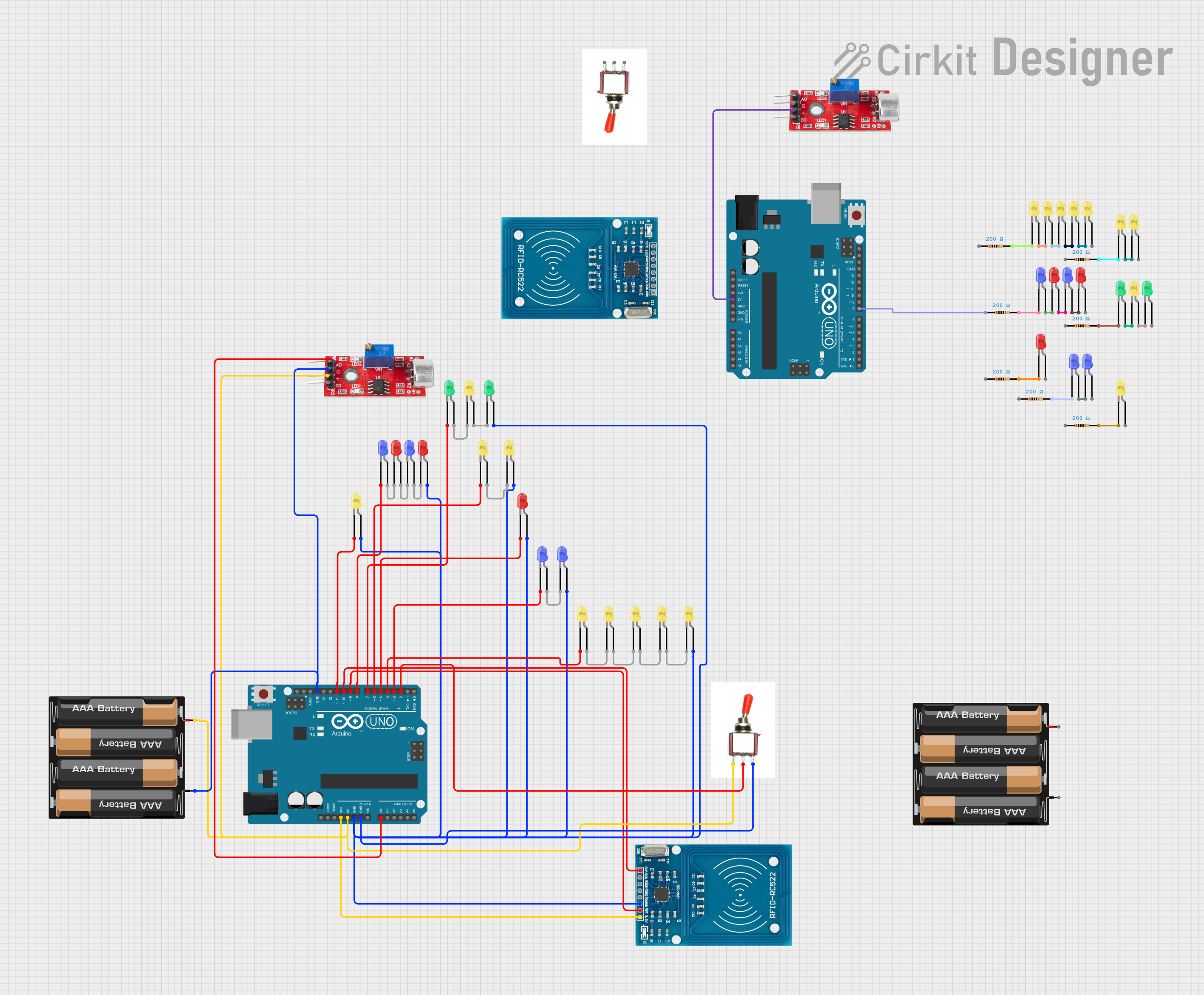
Circuit Documentation
Summary
The circuit in question appears to be a microcontroller-based system utilizing two Arduino UNO boards. The system includes a variety of components such as LEDs of different colors, resistors, a sound sensor, RFID-RC522 modules, a toggle switch, and battery mounts. The circuit is designed to operate with a power supply from the 4 x AAA battery mounts. The microcontrollers are programmed to interact with the connected components, likely to control the LEDs and communicate with the RFID modules based on the input from the sound sensor and the toggle switch.
Component List
Microcontrollers
- Arduino UNO: A microcontroller board based on the ATmega328P. It has 14 digital input/output pins, 6 analog inputs, a 16 MHz quartz crystal, a USB connection, a power jack, an ICSP header, and a reset button.
Sensors
- Sound Sensor: A device that can detect the intensity of sound and provide an analog or digital output.
Communication Modules
- RFID-RC522: An RFID reader/writer module that operates at 13.56 MHz.
Input Devices
- Toggle Switch: A switch that can open or close the circuit it is connected to.
Power Supplies
- 4 x AAA Battery Mount: A battery holder for four AAA batteries, providing a power source for the circuit.
Indicators
- LED: Two Pin (yellow, red, green, blue): Light Emitting Diodes of various colors used as visual indicators.
Passive Components
- Resistor: A passive two-terminal electrical component that implements electrical resistance as a circuit element.
Wiring Details
Arduino UNO
- 3.3V: Powers the RFID-RC522 module.
- 5V: Connected to the positive terminal of the battery mount, sound sensor, and other Arduino UNO.
- GND: Common ground for the circuit, connected to various LEDs, RFID-RC522, and sound sensor.
- Vin: Not used in this circuit.
- Digital Pins (D2-D13): Control various LEDs, toggle switch, and communicate with RFID-RC522.
- Analog Pins (A0-A5): A0 is used to read analog values from the sound sensor.
Sound Sensor
- VCC: Connected to the 5V supply from the Arduino UNO.
- GND: Connected to the common ground.
- Analog: Connected to the A0 analog input on the Arduino UNO.
- Digital: Not used in this circuit.
RFID-RC522
- VCC (3.3V): Powered by the 3.3V output from the Arduino UNO.
- RST: Reset pin controlled by the Arduino UNO.
- GND: Connected to the common ground.
- IRQ: Not used in this circuit.
- MISO, MOSI, SCK, SDA: SPI communication with the Arduino UNO.
Toggle Switch
- Vcc: Connected to the positive terminal of the battery mount.
- Sig: Signal pin connected to a digital input on the Arduino UNO.
- Gnd: Connected to the common ground.
LEDs
- Anode: Connected to the common ground through a resistor.
- Cathode: Controlled by various digital outputs on the Arduino UNO.
Resistor
- Pin1 and Pin2: Connected in series with LEDs to limit the current.
Documented Code
Arduino UNO (First Instance)
void setup() {
  // put your setup code here, to run once:

}

void loop() {
  // put your main code here, to run repeatedly:

}
Arduino UNO (Second Instance)
void setup() {
  // put your setup code here, to run once:

}

void loop() {
  // put your main code here, to run repeatedly:

}
Note: The provided code for both Arduino UNO instances is a template with no specific functionality. The actual behavior of the microcontrollers will depend on the code that is written and uploaded to them.