Cirkit Designer
Your all-in-one circuit design IDE
Home /
Project Documentation
ESP8266 NodeMCU-Controlled Smart Water Management System

Circuit Documentation
Summary of the Circuit
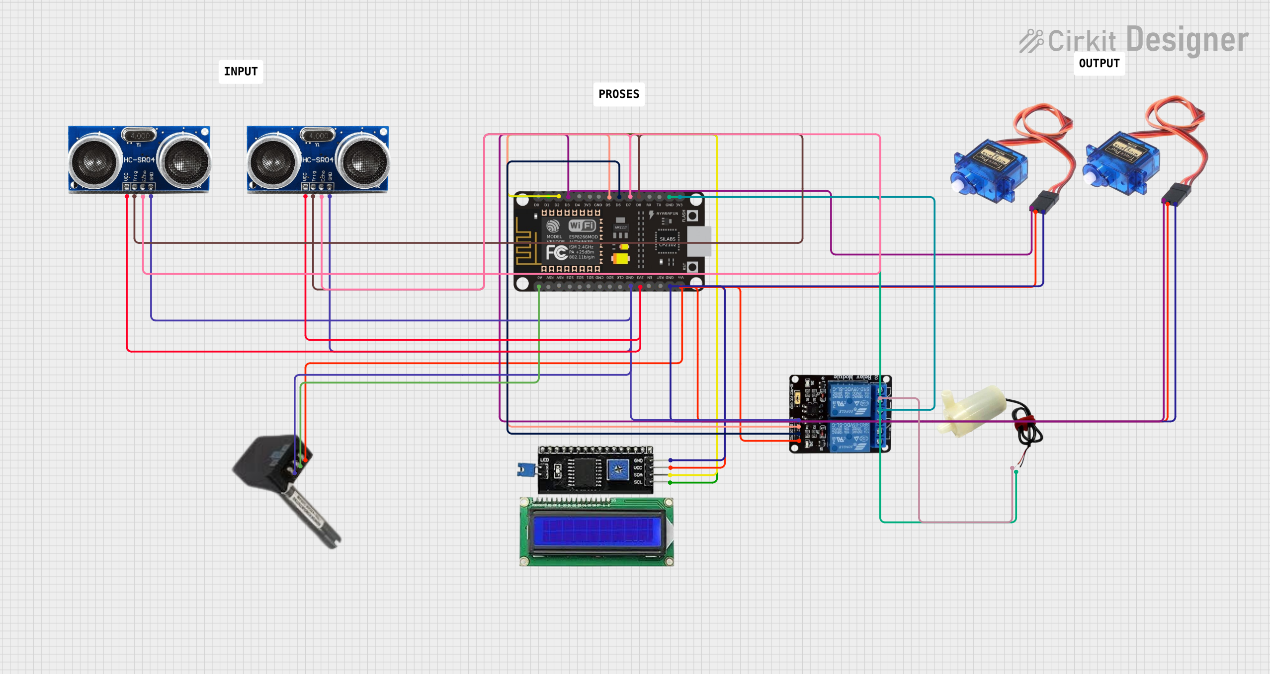
This circuit is designed to interface various sensors and actuators with an ESP8266 NodeMCU microcontroller. The components include two ultrasonic sensors, a TDS (Total Dissolved Solids) sensor, an I2C LCD display, a 5V mini water pump, two servo motors, and a relay module. The ESP8266 NodeMCU serves as the central processing unit, reading sensor data, controlling the LCD for display, and managing the actuators based on the sensor inputs and programmed logic.
Component List
Sensor TDS
- Pins: VCC, OUTPUT, GND
- Description: A sensor used to measure the total dissolved solids in water.
Sensor Ultrasonic
- Pins: VCC, Trig, Echo, GND
- Description: A sensor used to measure distance using ultrasonic waves.
LCD I2C
- Pins: GND, SCL, VCC, SDA
- Description: A liquid crystal display that uses the I2C protocol for communication.
5V Mini Water Pump
- Pins: Positive pin, Negative pin
- Description: A small pump used for moving water.
Servo Motor
- Pins: Ground, Power, Signal
- Description: An actuator capable of precise angular positioning.
ESP8266 NodeMCU
- Pins: D0, D1, D2, D3, D4, 3V3, GND, D5, D6, D7, D8, RX, TX, A0, RSV, SD3, SD2, SD1, CMD, SD0, CLK, EN, RST, VIN
- Description: A Wi-Fi capable microcontroller with digital and analog pins for interfacing with various components.
Relay
- Pins: COM, NO, VCC, IN2, GND, IN1
- Description: An electrically operated switch that allows for controlling high power devices.
Wiring Details
Sensor TDS
- VCC: Connected to the power supply net.
- OUTPUT: Connected to the A0 pin on the ESP8266 NodeMCU.
- GND: Connected to the ground net.
Sensor Ultrasonic (Two Instances)
- VCC: Connected to the 3V3 net from the ESP8266 NodeMCU.
- Trig: Both Trig pins connected to the D8 pin on the ESP8266 NodeMCU.
- Echo: Both Echo pins connected to the D7 pin on the ESP8266 NodeMCU.
- GND: Connected to the ground net.
LCD I2C
- GND: Connected to the ground net.
- SCL: Connected to the D1 pin on the ESP8266 NodeMCU.
- VCC: Connected to the power supply net.
- SDA: Connected to the D2 pin on the ESP8266 NodeMCU.
5V Mini Water Pump
- Positive Pin: Connected to the COM pin on the Relay.
- Negative Pin: Connected to the ground net.
Servo Motor (Two Instances)
- Ground: Connected to the ground net.
- Power: Connected to the power supply net.
- Signal: Both Signal pins connected to the D3 pin on the ESP8266 NodeMCU.
ESP8266 NodeMCU
- VIN: Connected to the power supply net.
- 3V3: Powers the ultrasonic sensors and the relay's NO pin.
- GND: Common ground for all components.
- D0-D8, RX, TX, A0, RSV, SD3, SD2, SD1, CMD, SD0, CLK, EN, RST: Various control and communication pins used for interfacing with the components.
Relay
- COM: Connected to the positive pin of the 5V mini water pump.
- NO: Connected to the 3V3 net from the ESP8266 NodeMCU.
- VCC: Connected to the power supply net.
- IN2: Connected to the D6 pin on the ESP8266 NodeMCU.
- GND: Connected to the ground net.
- IN1: Connected to the D5 pin on the ESP8266 NodeMCU.
Documented Code
No code has been provided for the microcontroller. The documentation of the code would typically include a description of the functionality, setup, and loop routines, along with any functions or libraries used to interface with the components listed above.