
Arduino UNO Controlled I2C LCD Display and Relay Switching System
View and Edit Project In Cirkit Designer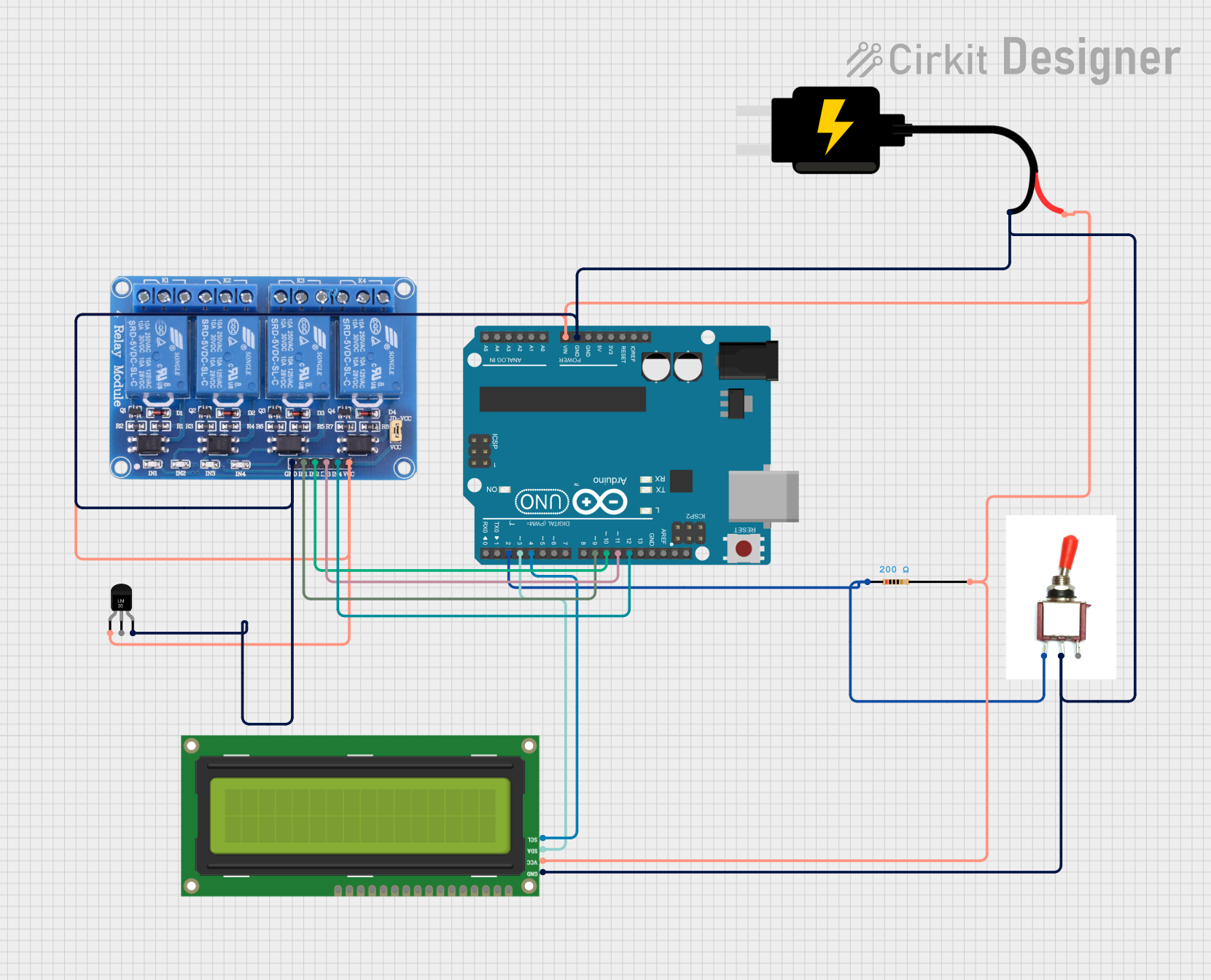
Circuit Documentation
Summary of the Circuit
This circuit is designed to interface an Arduino UNO with an I2C LCD screen, a toggle switch, a 4-channel relay module, and a temperature sensor (LM35). The Arduino UNO serves as the central processing unit, controlling the relay states based on the input from the toggle switch and displaying messages on the LCD screen. The relay module allows for controlling high-power devices, while the temperature sensor provides environmental feedback. The circuit is powered by a 5V DC source, and a resistor is included to provide current limiting or voltage division as required.
Component List
Arduino UNO
- Microcontroller board based on the ATmega328P
- Provides digital and analog I/O pins
- Can be programmed via USB connection
Toggle Switch
- A simple switch that can open or close a circuit
- Used to provide input to the Arduino
I2C LCD 16x2 Screen
- A 16-character by 2-line display with an I2C interface
- Used for displaying information
Resistor
- A passive two-terminal electrical component
- Implements electrical resistance as a circuit element
DC Source 5V
- Provides a 5V power supply to the circuit
Relay 4 Channel 5v
- A 4-channel relay module that can control up to four separate high-power circuits
- Operates at 5V
Temperature Sensor (LM35)
- An analog temperature sensor
- Provides voltage output proportional to the temperature
Wiring Details
Arduino UNO
- GND connected to the common ground net
- Vin connected to the 5V power supply through a resistor
- D2 connected to one side of the toggle switch
- D9, D10, D11, D12 connected to relay module inputs IN1, IN2, IN3, IN4 respectively
- D3 (SDA) and D4 (SCL) connected to the I2C LCD screen
Toggle Switch
- Vcc connected to the 5V power supply through a resistor
- Sig connected to Arduino UNO pin D2
I2C LCD 16x2 Screen
- SCL connected to Arduino UNO pin D4
- SDA connected to Arduino UNO pin D3
- VCC (5V) and GND connected to the 5V power supply and common ground net respectively
Resistor
- Connected between the 5V power supply and the toggle switch, and Arduino UNO Vin
DC Source 5V
- VCC connected to the 5V power rail
- GND connected to the common ground net
Relay 4 Channel 5v
- VCC connected to the 5V power supply
- GND connected to the common ground net
- IN1, IN2, IN3, IN4 connected to Arduino UNO pins D9, D10, D11, D12 respectively
Temperature Sensor (LM35)
- +Vs connected to the 5V power supply
- GND connected to the common ground net
- Vout not connected in the provided net list
Documented Code
/*
 * Arduino UNO Interface with I2C LCD
 * This code initializes the I2C LCD and displays a message.
 * It also reads the state of a toggle switch and controls a relay based on the switch state.
 */

#include <Wire.h>
#include <LiquidCrystal_I2C.h>

// Initialize the LCD with I2C address 0x27 and 16x2 display
LiquidCrystal_I2C lcd(0x27, 16, 2);

// Pin definitions
const int toggleSwitchPin = 2;
const int relayPin1 = 9;
const int relayPin2 = 10;
const int relayPin3 = 11;
const int relayPin4 = 12;

void setup() {
  // Initialize the LCD
  lcd.begin();
  lcd.backlight();
  lcd.setCursor(0, 0);
  lcd.print("Hello, World!");

  // Initialize the toggle switch pin
  pinMode(toggleSwitchPin, INPUT);

  // Initialize relay pins
  pinMode(relayPin1, OUTPUT);
  pinMode(relayPin2, OUTPUT);
  pinMode(relayPin3, OUTPUT);
  pinMode(relayPin4, OUTPUT);

  // Set all relays to off
  digitalWrite(relayPin1, LOW);
  digitalWrite(relayPin2, LOW);
  digitalWrite(relayPin3, LOW);
  digitalWrite(relayPin4, LOW);
}

void loop() {
  // Read the state of the toggle switch
  int switchState = digitalRead(toggleSwitchPin);

  // Control the relay based on the switch state
  if (switchState == HIGH) {
    digitalWrite(relayPin1, HIGH);
  } else {
    digitalWrite(relayPin1, LOW);
  }

  // Add more logic here if needed
}
This code is designed to run on the Arduino UNO and controls the relay module based on the state of the toggle switch. It also initializes the I2C LCD and displays a greeting message. The code is structured with setup and loop functions, typical of Arduino sketches.