
ESP8266 NodeMCU Controlled Relay Module for Smart AC Lighting
View and Edit Project In Cirkit Designer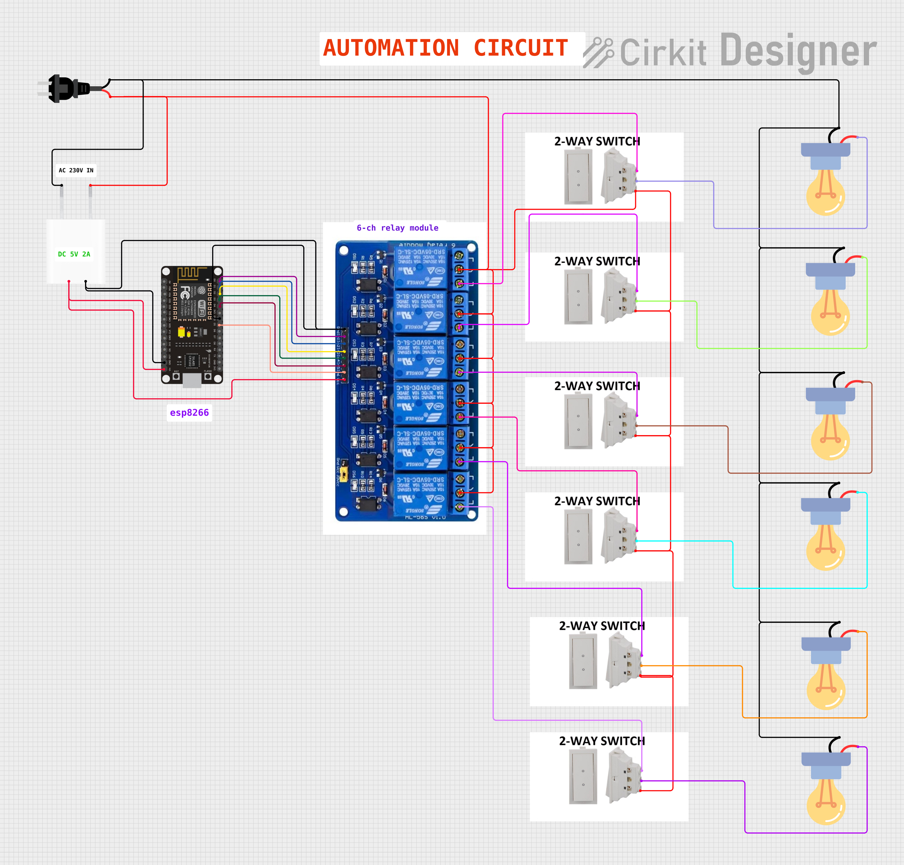
Circuit Documentation
Summary
This circuit is designed to control multiple AC-powered LED bulbs using an ESP8266 NodeMCU microcontroller and a 6-relay module. The ESP8266 NodeMCU is interfaced with the relay module to switch the LED bulbs on and off. The power for the NodeMCU and the relay module is supplied by a 5V adapter. The AC power source is connected to the relay module and LED bulbs through two-way electrical switches, allowing manual control over the lighting in addition to the microcontroller's control.
Component List
ESP8266 NodeMCU
- Microcontroller with WiFi capability.
- Pins: D0, D1, D2, D3, D4, 3V3, GND, D5, D6, D7, D8, RX, TX, A0, RSV, SD3, SD2, SD1, CMD, SD0, CLK, EN, RST, VIN.
6 Relays Module
- Module with 6 individual relays capable of controlling high power devices.
- Pins: GND, IN1, IN2, IN3, IN4, IN5, IN6, VCC, NC_2, COM_2, NO_2, NC_3, COM_3, NO_3, NC_4, COM_4, NO_4, NC_5, COM_5, NO_5, NC_6, COM_6, NO_6, NC_1, COM_1, NO_1.
5V Adapter
- Power supply adapter converting AC to 5V DC.
- Pins: AC In 1, AC In 2, 5V, GND.
LED Bulb AC / Bombillo AC
- AC-powered LED bulbs for lighting.
- Pins: +, -.
AC Source
- The main AC power supply for the circuit.
- Pins: -, +.
Two-Way Electrical Switch
- Manual switch to control the flow of AC power.
- Pins: 1, 2, 3.
Wiring Details
ESP8266 NodeMCU
- D0 connected to Relay Module IN1.
- D1 connected to Relay Module IN2.
- D2 connected to Relay Module IN3.
- D3 connected to Relay Module IN4.
- D4 connected to Relay Module IN5.
- GND connected to 5V Adapter GND and Relay Module GND.
- D5 connected to Relay Module IN6.
- VIN connected to 5V Adapter 5V and Relay Module VCC.
6 Relays Module
- GND connected to ESP8266 NodeMCU GND and 5V Adapter GND.
- IN1 to IN6 connected to corresponding ESP8266 NodeMCU D0 to D5 pins.
- VCC connected to 5V Adapter 5V and ESP8266 NodeMCU VIN.
- COM_1 to COM_6 connected to AC Source +.
- NO_1 to NO_6 connected to Two-Way Electrical Switches pin 1.
5V Adapter
- AC In 1 connected to AC Source -.
- AC In 2 connected to AC Source +.
- 5V connected to ESP8266 NodeMCU VIN and Relay Module VCC.
- GND connected to ESP8266 NodeMCU GND and Relay Module GND.
LED Bulb AC / Bombillo AC
- Each LED bulb's - pin connected to AC Source -.
- Each LED bulb's + pin connected to corresponding Two-Way Electrical Switch pin 2.
AC Source
-
- connected to 5V Adapter AC In 2 and Two-Way Electrical Switches pin 3.
-
- connected to 5V Adapter AC In 1 and all LED bulbs' - pins.
Two-Way Electrical Switch
- Pin 1 connected to corresponding Relay Module NO_x pin.
- Pin 2 connected to corresponding LED bulb + pin.
- Pin 3 connected to AC Source +.
Documented Code
The code for the ESP8266 NodeMCU is not provided in the input. However, the typical code structure for controlling a relay module with an ESP8266 NodeMCU would include setting up the GPIO pins as outputs and toggling them to control the state of the relays. The code would also include WiFi setup to allow remote control through a network.
// Placeholder for actual ESP8266 NodeMCU code
void setup() {
  // Initialize digital pins as outputs
  pinMode(D0, OUTPUT);
  pinMode(D1, OUTPUT);
  pinMode(D2, OUTPUT);
  pinMode(D3, OUTPUT);
  pinMode(D4, OUTPUT);
  pinMode(D5, OUTPUT);
  // Initialize all relays to OFF state
  digitalWrite(D0, LOW);
  digitalWrite(D1, LOW);
  digitalWrite(D2, LOW);
  digitalWrite(D3, LOW);
  digitalWrite(D4, LOW);
  digitalWrite(D5, LOW);
}

void loop() {
  // Code to control relays based on some conditions or inputs
}
Please note that the actual code would need to be written and uploaded to the ESP8266 NodeMCU to control the relays based on the desired logic and conditions.