Arduino-Controlled Line-Following Robot with Dual TCS3200 Color Sensors
Circuit Documentation
Summary
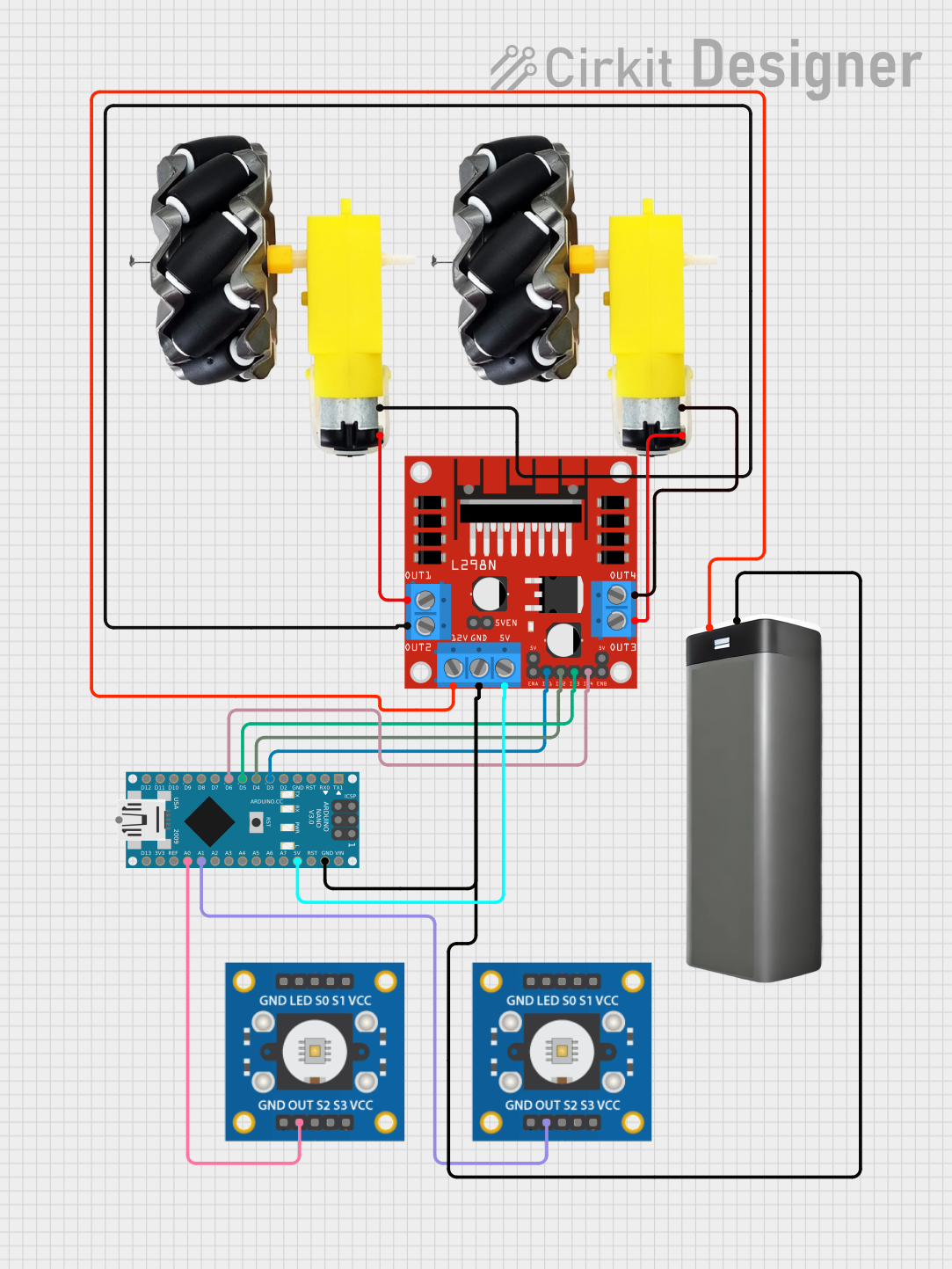
This circuit is designed to control a pair of motors using an L298N DC motor driver, interfaced with an Arduino Nano microcontroller. The Arduino Nano reads inputs from two TCS3200 color sensors and drives the motors based on the sensor readings to perform line following or obstacle avoidance tasks. The motor driver is powered by a battery pack, and the Arduino Nano controls the motor driver through digital output pins.
Component List
L298N DC Motor Driver
- Description: A motor driver module capable of driving two DC motors.
- Pins: OUT1, OUT2, 12V, GND, 5V, OUT3, OUT4, ENA, IN1, IN2, IN3, IN4, ENB.
TCS3200 Color Sensor
- Description: A color sensor module that outputs a frequency corresponding to the color it detects.
- Pins: GND, OUT, S2, S3, VCC, LED, S0, S1.
Battery Pack
- Description: A power source for the circuit.
- Pins: + (positive), - (negative).
Arduino Nano
- Description: A compact microcontroller board based on the ATmega328P.
- Pins: D1/TX, D0/RX, RESET, GND, D2, D3, D4, D5, D6, D7, D8, D9, D10, D11/MOSI, D12/MISO, VIN, 5V, A7, A6, A5, A4, A3, A2, A1, A0, AREF, 3V3, D13/SCK.
Motor and Wheels
- Description: The actuator of the circuit, which converts electrical energy into mechanical motion.
- Pins: vcc, GND.
Wiring Details
L298N DC Motor Driver
- OUT1 connected to Motor 1 (vcc)
- OUT2 connected to Motor 1 (GND)
- OUT3 connected to Motor 2 (vcc)
- OUT4 connected to Motor 2 (GND)
- 12V connected to Battery Pack (+)
- GND connected to Battery Pack (-) and Arduino Nano (GND)
- 5V connected to Arduino Nano (5V)
- IN1 connected to Arduino Nano (D3)
- IN2 connected to Arduino Nano (D4)
- IN3 connected to Arduino Nano (D5)
- IN4 connected to Arduino Nano (D6)
TCS3200 Color Sensor
- OUT connected to Arduino Nano (A0) for the first sensor
- OUT connected to Arduino Nano (A1) for the second sensor
- VCC connected to a power source (not specified in the net list)
- GND connected to a common ground (not specified in the net list)
Battery Pack
- (+) connected to L298N DC Motor Driver (12V)
- (-) connected to L298N DC Motor Driver (GND), Arduino Nano (GND)
Arduino Nano
- D3 connected to L298N DC Motor Driver (IN1)
- D4 connected to L298N DC Motor Driver (IN2)
- D5 connected to L298N DC Motor Driver (IN3)
- D6 connected to L298N DC Motor Driver (IN4)
- A0 connected to TCS3200 Color Sensor (OUT) for the first sensor
- A1 connected to TCS3200 Color Sensor (OUT) for the second sensor
- 5V connected to L298N DC Motor Driver (5V)
- GND connected to Battery Pack (-) and L298N DC Motor Driver (GND)
Motor and Wheels
- Motor 1 (vcc) connected to L298N DC Motor Driver (OUT1)
- Motor 1 (GND) connected to L298N DC Motor Driver (OUT2)
- Motor 2 (vcc) connected to L298N DC Motor Driver (OUT3)
- Motor 2 (GND) connected to L298N DC Motor Driver (OUT4)
Documented Code
// Motor pins
const int leftMotorForward = 3;
const int leftMotorBackward = 4;
const int rightMotorForward = 5;
const int rightMotorBackward = 6;

// Sensor pins
const int leftSensor = A0;
const int rightSensor = A1;

// Threshold for detecting the line
const int threshold = 500; // Adjust based on your sensors

void setup() {
  pinMode(leftMotorForward, OUTPUT);
  pinMode(leftMotorBackward, OUTPUT);
  pinMode(rightMotorForward, OUTPUT);
  pinMode(rightMotorBackward, OUTPUT);

  pinMode(leftSensor, INPUT);
  pinMode(rightSensor, INPUT);
}

void loop() {
  int leftValue = analogRead(leftSensor);
  int rightValue = analogRead(rightSensor);

  if (leftValue < threshold && rightValue < threshold) {
    // Move forward if both sensors see the line
    moveForward();
  } else if (leftValue < threshold) {
    // Turn right if only the left sensor sees the line
    turnRight();
  } else if (rightValue < threshold) {
    // Turn left if only the right sensor sees the line
    turnLeft();
  } else {
    // Stop if neither sensor sees the line
    stop();
  }
}

void moveForward() {
  digitalWrite(leftMotorForward, HIGH);
  digitalWrite(leftMotorBackward, LOW);
  digitalWrite(rightMotorForward, HIGH);
  digitalWrite(rightMotorBackward, LOW);
}

void turnRight() {
  digitalWrite(leftMotorForward, HIGH);
  digitalWrite(leftMotorBackward, LOW);
  digitalWrite(rightMotorForward, LOW);
  digitalWrite(rightMotorBackward, HIGH);
}

void turnLeft() {
  digitalWrite(leftMotorForward, LOW);
  digitalWrite(leftMotorBackward, HIGH);
  digitalWrite(rightMotorForward, HIGH);
  digitalWrite(rightMotorBackward, LOW);
}

void stop() {
  digitalWrite(leftMotorForward, LOW);
  digitalWrite(leftMotorBackward, LOW);
  digitalWrite(rightMotorForward, LOW);
  digitalWrite(rightMotorBackward, LOW);
}
This code is designed to be uploaded to the Arduino Nano microcontroller. It sets up the motor control pins and sensor input pins, then continuously reads the sensor values in the loop() function. Based on the sensor readings, it controls the motors to move forward, turn left, turn right, or stop. The threshold value is used to determine whether the sensors detect the line or not, and should be calibrated based on the actual sensor readings obtained from the environment.