
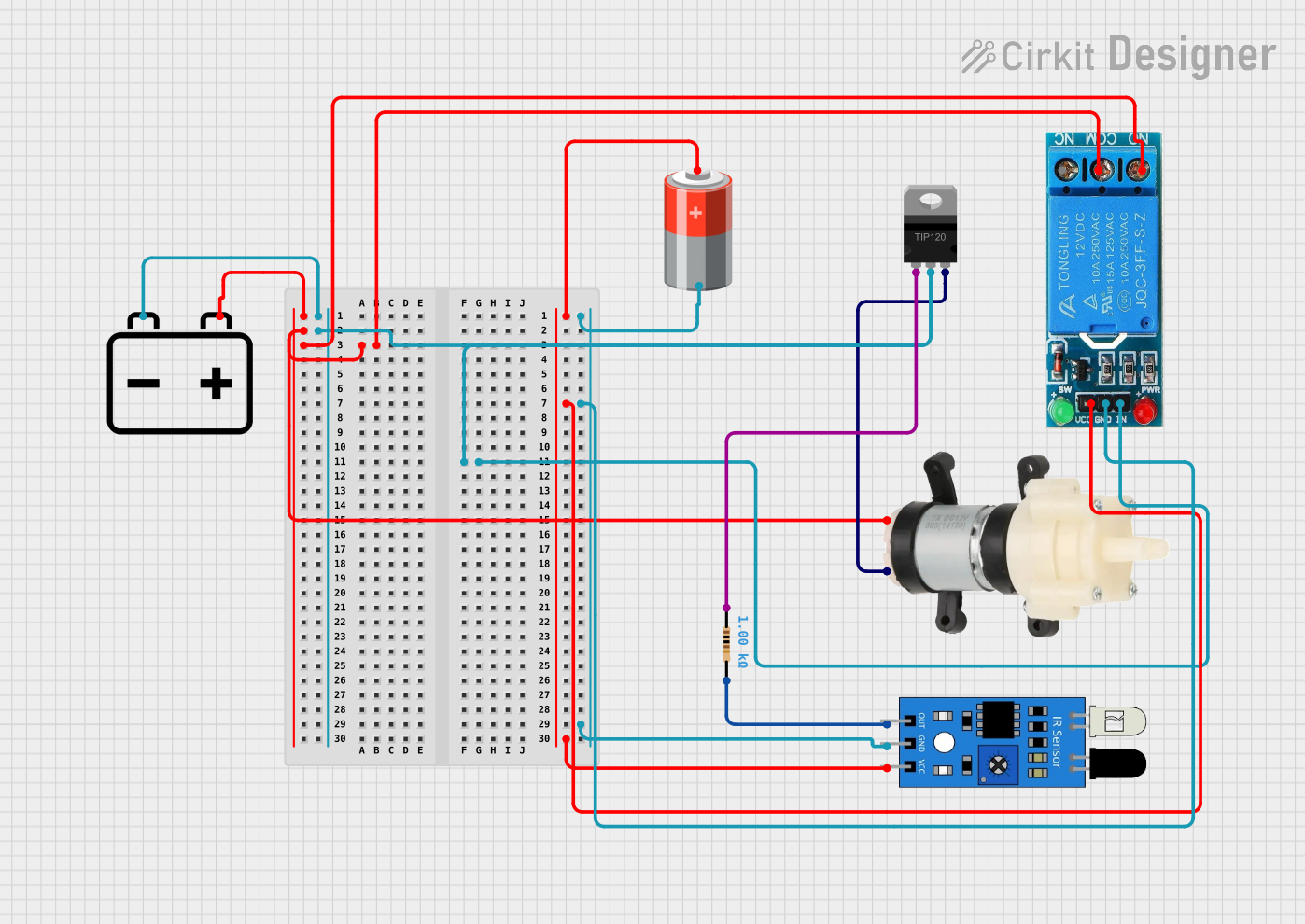
Circuit Documentation
Summary of the Circuit
This circuit appears to be designed to control a Mini Diaphragm Water Pump using a 12V power supply and an IR sensor for triggering. The pump is controlled through a 12V single-channel relay, which is in turn driven by a TIP120 high-current Darlington transistor. The transistor is controlled by the output of the IR sensor, which is presumably detecting some form of input to activate the pump. A resistor is used to limit the current to the base of the transistor. The circuit also includes a separate 5V power supply that powers the IR sensor and the relay's control circuitry.
Component List
12v Battery
- Description: Provides the main power source for the relay and the water pump.
- Pins:
+,-
5v Battery
- Description: Supplies power to the IR sensor and the relay control circuit.
- Pins:
+,-
Mini Diaphragm Water Pump
- Description: The actuator in the circuit, responsible for pumping water when activated.
- Pins:
Positive (+),Negative (-)
TIP120 Hi-Current Darlington Transistor
- Description: Acts as a switch to control high current loads with a low current signal.
- Pins:
BASE,COLLECTOR,EMITTER
IR Sensor
- Description: Senses the presence of an object or movement, providing a signal to control the transistor.
- Pins:
out,gnd,vcc
Resistor
- Description: Limits the current flowing into the transistor's base.
- Pins:
pin1,pin2 - Properties:
Resistance: 1000 Ohms
12V Single Channel Relay
- Description: Electrically operated switch that allows the water pump to be turned on or off.
- Pins:
NC,COM,NO,IN,GND,VCC
Wiring Details
12v Battery
+connected to theCOMpin of the 12V Single Channel Relay andPositive (+)pin of the Mini Diaphragm Water Pump.-connected to theINpin of the 12V Single Channel Relay andCOLLECTORpin of the TIP120 Transistor.
5v Battery
+connected to theVCCpin of the 12V Single Channel Relay andvccpin of the IR Sensor.-connected to theGNDpin of the 12V Single Channel Relay andgndpin of the IR Sensor.
Mini Diaphragm Water Pump
Positive (+)connected to the+of the 12v Battery andNOpin of the 12V Single Channel Relay.Negative (-)connected to theEMITTERpin of the TIP120 Transistor.
TIP120 Hi-Current Darlington Transistor
BASEconnected topin1of the Resistor.COLLECTORconnected to the-of the 12v Battery.EMITTERconnected to theNegative (-)pin of the Mini Diaphragm Water Pump.
IR Sensor
outconnected topin2of the Resistor.gndconnected to the-of the 5v Battery.vccconnected to the+of the 5v Battery.
Resistor
pin1connected to theBASEpin of the TIP120 Transistor.pin2connected to theoutpin of the IR Sensor.
12V Single Channel Relay
NCnot connected in this circuit.COMconnected to the+of the 12v Battery.NOconnected to thePositive (+)pin of the Mini Diaphragm Water Pump.INconnected to the-of the 12v Battery.GNDconnected to the-of the 5v Battery.VCCconnected to the+of the 5v Battery.
Documented Code
There is no code provided for any microcontrollers in this circuit. If the circuit is intended to be controlled by a microcontroller, the code would be necessary to define the behavior of the IR sensor and the subsequent activation of the relay and water pump. Without the code, the circuit's operation is assumed to be purely hardware-based, with the IR sensor directly controlling the transistor and relay.