
Arduino-Controlled RGB Traffic Light with Stepper Motor Actuation
View and Edit Project In Cirkit Designer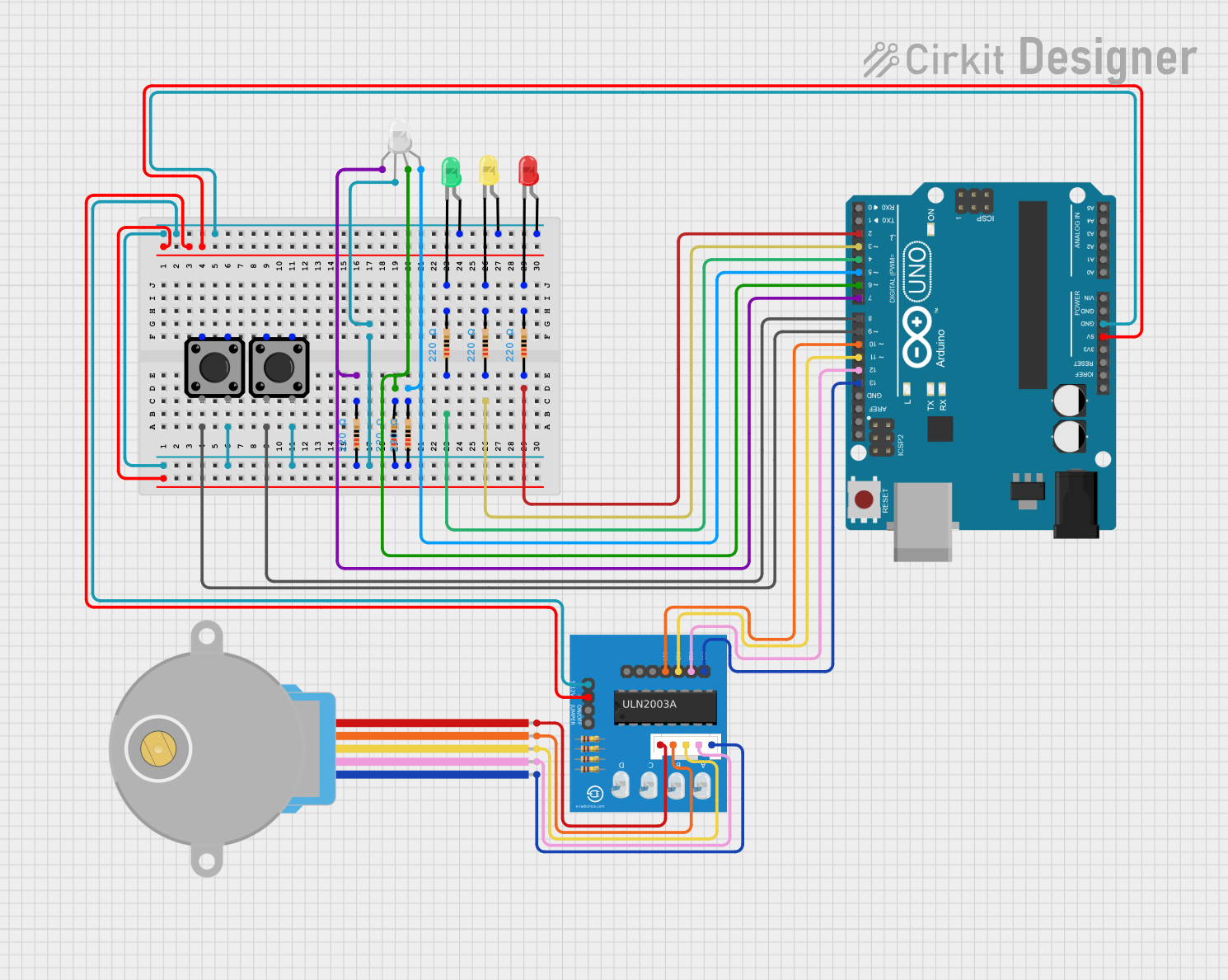
Circuit Documentation
Summary
The circuit in question appears to be a control system utilizing an Arduino UNO microcontroller to manage the operation of a stepper motor and a series of LEDs, including an RGB LED. The system is designed to respond to button presses, with the capability to control the stepper motor's operation and the state of the LEDs. The circuit includes resistors for current limiting, tactile switch buttons for user input, and a ULN2003A breakout board to drive the stepper motor.
Component List
Microcontroller
- Arduino UNO: A microcontroller board based on the ATmega328P, featuring digital input/output pins, analog inputs, a USB connection for programming, and power management capabilities.
Resistors
- 220 Ohm Resistors: Used for current limiting to protect LEDs and to ensure proper operation within the circuit.
Tactile Switch Buttons
- Tactile Switch Buttons - 12mm Square: Provide user input to the system, allowing control over the stepper motor and LEDs.
LEDs
- LED (Green, Yellow, Red): Visual indicators that can be used to display the status of the system or provide feedback to the user.
- RGB LED (Wokwi compatible): A multi-color LED capable of displaying a variety of colors by mixing red, green, and blue light.
Motor Driver
- ULN2003A breakout board: Used to drive the stepper motor with higher current and voltage than the microcontroller can provide directly.
Stepper Motor
- 28BYJ-48 Stepper Motor: A small, 5-wire, unipolar stepper motor used for precise motion control.
Wiring Details
Arduino UNO
- Digital pins D2-D13 are used for controlling the LEDs and the stepper motor via the ULN2003A breakout board.
- The 5V and GND pins provide power to the ULN2003A breakout board and common ground for the circuit.
220 Ohm Resistors
- Connected in series with the LEDs to limit the current through them.
Tactile Switch Buttons
- Wired to provide input signals to the Arduino UNO when pressed.
LEDs (Green, Yellow, Red)
- The anodes are connected to the positive side of the power supply through current-limiting resistors.
- The cathodes are connected to the ground.
RGB LED (Wokwi compatible)
- The common pin (COM) is connected to the ground.
- The R, G, and B pins are connected to the Arduino UNO through current-limiting resistors to control the color output.
ULN2003A breakout board
- Inputs (In 1-In 4) are connected to the Arduino UNO digital pins D10-D13.
- The 0V and +5V pins are connected to the ground and 5V from the Arduino UNO, respectively.
- The output wires (BLUE, PINK, YELLOW, ORANGE, RED) are connected to the corresponding wires of the 28BYJ-48 Stepper Motor.
28BYJ-48 Stepper Motor
- The wires are connected to the ULN2003A breakout board to receive the control signals for stepping.
Documented Code
The code provided is for the Arduino UNO microcontroller and is written in C++ using the Arduino IDE. The code includes a library for controlling stepper motors and defines several constants for pin assignments and system parameters. The setup() function initializes the system, and the loop() function continuously checks for button presses and updates the system state accordingly.
The system can be in one of several states: OFF, STANDBY, RUNNING, PAUSED, or RESET. Button presses can change the state, and the system behavior changes depending on the current state. The stepper motor's operation and the LEDs' states are controlled based on the system state and button inputs.
The code includes functions for handling short and long button presses, updating the system state, controlling the stepper motor and LEDs, and printing the system status to the serial monitor.
// Code omitted for brevity. Please refer to the provided code for details.
The code is structured with clear function definitions and comments explaining the purpose of each part of the code. This makes it easier to understand and modify if necessary.