Arduino UNO Based Multi-Temperature Sensing with OLED Display and SD Logging
Circuit Documentation
Summary
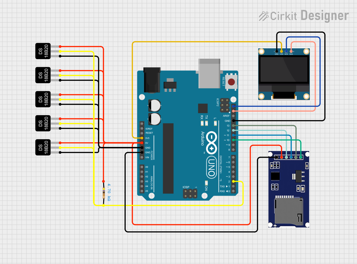
This circuit integrates an Arduino UNO microcontroller with multiple peripherals, including a 0.96" OLED display, an SD card module, and several DS18B20 temperature sensors. The Arduino UNO serves as the central processing unit, managing data communication between the sensors, the display, and the SD card module. The temperature sensors are connected in a parallel configuration, sharing a common data line with a pull-up resistor. The OLED display and SD card module are interfaced with the Arduino using SPI communication. The circuit is designed to monitor temperatures, display data on the OLED, and log data to an SD card.
Component List
Arduino UNO
- Microcontroller board based on the ATmega328P
- Provides digital I/O pins, analog inputs, and various power outputs
DS18B20 Temperature Sensor (Wokwi Compatible)
- Digital temperature sensor with a unique one-wire interface
- Allows for multiple sensors to be connected on the same data line
Resistor
- 4.7k Ohm resistor used as a pull-up for the one-wire data line of the DS18B20 sensors
0.96" OLED
- Small display module for visual output
- Uses I2C communication protocol
SD Card Module
- Peripheral for data logging on an SD card
- Interfaces with the Arduino via SPI communication
Wiring Details
Arduino UNO
3.3Vsupplies power to the 0.96" OLED display5Vsupplies power to the DS18B20 sensors and the SD card moduleGNDis the common ground for all componentsSCL(A5) connects to theSCKof the OLED for I2C communicationSDA(A4) connects to theSDAof the OLED for I2C communicationD13connects to theSCKof the SD card module for SPI communicationD12connects to theMISOof the SD card module for SPI communicationD11connects to theMOSIof the SD card module for SPI communicationD10connects to theCSof the SD card module for SPI communicationD2connects to the data line (DQ) of all DS18B20 sensors through a 4.7k Ohm pull-up resistor
DS18B20 Temperature Sensors
- All sensors have their
VCCpins connected to the Arduino's5V - All sensors have their
GNDpins connected to the Arduino'sGND - All sensors share a common data line (
DQ) connected to Arduino'sD2through a 4.7k Ohm pull-up resistor
Resistor
- One end connected to the data line (
DQ) of the DS18B20 sensors - The other end connected to the Arduino's
5Vto serve as a pull-up
0.96" OLED
VDDconnected to the Arduino's3.3VGNDconnected to the Arduino'sGNDSCKconnected to the Arduino'sSCL(A5) for I2C communicationSDAconnected to the Arduino'sSDA(A4) for I2C communication
SD Card Module
VCCconnected to the Arduino's5VGNDconnected to the Arduino'sGNDSCKconnected to the Arduino'sD13for SPI communicationMISOconnected to the Arduino'sD12for SPI communicationMOSIconnected to the Arduino'sD11for SPI communicationCSconnected to the Arduino'sD10for SPI communication
Documented Code
Arduino UNO Code (sketch.ino)
void setup() {
  // put your setup code here, to run once:

}

void loop() {
  // put your main code here, to run repeatedly:

}
The provided code is a template with empty setup() and loop() functions. The setup() function is intended for initialization code that runs once at startup, such as configuring pin modes or initializing communication protocols. The loop() function contains the main logic that will run continuously, such as reading sensor data, updating the display, and writing to the SD card. Specific implementation details need to be added to fulfill the circuit's intended functionality.