
Arduino Nano Controlled NRF24L01 Wireless Communication System
View and Edit Project In Cirkit Designer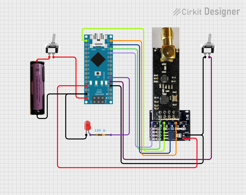
Circuit Documentation
Summary of the Circuit
This circuit is designed to utilize an Arduino Nano as the central microcontroller to interface with an NRF24L01 Adapter for wireless communication. The circuit includes a toggle switch to control power to the Arduino Nano and another toggle switch to act as an input for sending messages via the NRF24L01 module. A resistor and LED are connected to the Arduino Nano to provide visual feedback when a message is sent. The circuit is powered by a 3.7V power source.
Component List
NRF24L01 Adapter
- Description: A wireless communication module that operates in the 2.4 GHz band.
- Pins: CE, CSN, SCK, MOSI, MISO, IRQ, VCC, GND
Toggle Switch SPST (Single Pole Single Throw)
- Description: A switch that can connect or disconnect the circuit it is a part of.
- Pins: L1, COM
NRF24L01 Long Range
- Description: A long-range version of the NRF24L01 wireless communication module.
- Pins: Not specified in the provided list.
Resistor
- Description: A passive two-terminal electrical component that implements electrical resistance as a circuit element.
- Value: 100 Ohms
Arduino Nano
- Description: A small, complete, and breadboard-friendly board based on the ATmega328 (Arduino Nano 3.x).
- Pins: D1/TX, D0/RX, RESET, GND, D2, D3, D4, D5, D6, D7, D8, D9, D10, D11/MOSI, D12/MISO, VIN, 5V, A7, A6, A5, A4, A3, A2, A1, A0, AREF, 3V3, D13/SCK
LED: Two Pin (red)
- Description: A red light-emitting diode.
- Pins: cathode, anode
3.7V Power Source
- Description: A power source providing a voltage of 3.7V.
- Pins: +, -
Wiring Details
NRF24L01 Adapter
- CE connected to Arduino Nano D9
- CSN connected to Arduino Nano D10
- SCK connected to Arduino Nano D13/SCK
- MOSI connected to Arduino Nano D11/MOSI
- MISO connected to Arduino Nano D12/MISO
- VCC connected to Arduino Nano 5V
- GND connected to Arduino Nano GND
Toggle Switch SPST
- L1 connected to Arduino Nano GND
- COM connected to Arduino Nano D2
Resistor
- pin1 connected to LED anode
- pin2 connected to Arduino Nano D3
Arduino Nano
- D9 connected to NRF24L01 Adapter CE
- D10 connected to NRF24L01 Adapter CSN
- D13/SCK connected to NRF24L01 Adapter SCK
- D11/MOSI connected to NRF24L01 Adapter MOSI
- D12/MISO connected to NRF24L01 Adapter MISO
- 5V connected to NRF24L01 Adapter VCC
- GND connected to NRF24L01 Adapter GND, Toggle Switch SPST L1, and LED cathode
- D2 connected to Toggle Switch SPST COM
- D3 connected to Resistor pin2
- VIN connected to 3.7V Power Source +
- GND connected to 3.7V Power Source -
LED: Two Pin (red)
- cathode connected to Arduino Nano GND
- anode connected to Resistor pin1
3.7V Power Source
-
- connected to Arduino Nano VIN
-
- connected to Arduino Nano GND
Documented Code
#include "nRF24L01.h" // NRF24L01 library created by TMRh20 https://github.com/TMRh20/RF24
#include "RF24.h"
#include "SPI.h"
#define SwitchPin 2
#define LED_PIN 3
int SentMessage[1] = {000};
RF24 radio(9, 10); // NRF24L01 used SPI pins + Pin 9 and 10 on the NANO
const uint64_t pipe = 0xE6E6E6E6E6E6; // Needs to be the same for communicating between 2 NRF24L01

void setup()
{
  pinMode(SwitchPin, INPUT_PULLUP);
  digitalWrite(SwitchPin, HIGH);
  radio.begin(); // Start the NRF24L01
  radio.openWritingPipe(pipe); // Get NRF24L01 ready to transmit
  pinMode(LED_PIN, OUTPUT);
}

void loop()
{
  if (digitalRead(SwitchPin) == LOW)    // If switch is pressed
  {
    SentMessage[0] = 111;
    radio.write(SentMessage, 1);      // Send pressed data to NRF24L01
    digitalWrite(LED_PIN, HIGH);
  }
  else
  {
    SentMessage[0] = 000;
    radio.write(SentMessage, 1);      // Send idle data to NRF24L01
    digitalWrite(LED_PIN, LOW);
  }
}
This code is designed to run on the Arduino Nano. It initializes the NRF24L01 module and sets up a communication pipe. When the toggle switch connected to pin D2 is closed, the Arduino sends a message with the value 111 to the NRF24L01 module, and the LED connected to pin D3 is turned on. When the switch is open, it sends a message with the value 000 and turns the LED off.