
ESP32-Based Electric Grid Monitoring and Control System with TFT Display and NeoPixel Ring
View and Edit Project In Cirkit Designer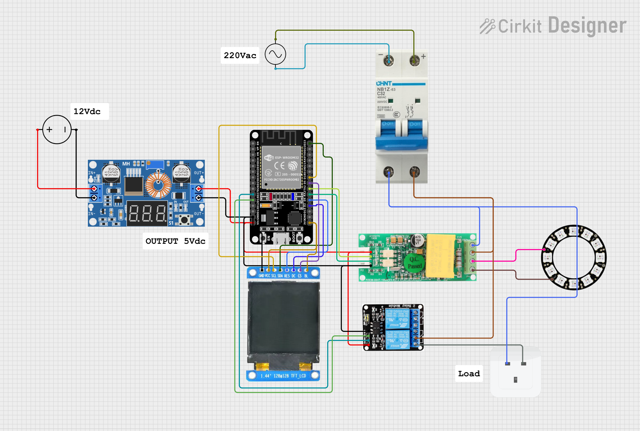
Circuit Documentation
Summary
This document provides a detailed overview of an electric grid monitoring and control system. The system includes various components such as relays, a TFT display, an energy monitor, a NeoPixel ring, and an ESP32 microcontroller. The system is designed to monitor and control the electric grid by measuring voltage, current, power, and energy, and displaying this information on a TFT screen. Additionally, it uses relays to control the grid based on the measured parameters and provides visual feedback using a NeoPixel ring.
Component List
5V 2-Relay JD-VCC
- Description: A relay module that allows control of high voltage devices using low voltage signals.
- Pins: JD-VCC, VCC, GND, IN1, IN2, NO, COM, NC
XL4015 5A DC Buck Step-down
- Description: A DC-DC buck converter that steps down voltage from a higher input to a lower output.
- Pins: Output +, Output -, Input +, Input -
DC Power Source
- Description: Provides DC power to the circuit.
- Pins: Ground, Positive
Ac Supply
- Description: Provides AC power to the circuit.
- Pins: +ve, -ve
Adafruit 12 NeoPixel Ring
- Description: A ring of 12 individually addressable RGB LEDs.
- Pins: OUT, VDD, IN, GND
PZEM004t
- Description: An energy monitor that measures voltage, current, power, and energy.
- Pins: VCC, RX, TX, GND, IN, OUT
Socket
- Description: A standard electrical socket.
- Pins: earth, life, neutral
ST7735 128x128 1.44 TFT I2C Color
- Description: A 1.44-inch TFT display with I2C interface.
- Pins: BL, C5, DC, RES, SDA, SCL, GND, VCC
ESP32 (30 pin)
- Description: A powerful microcontroller with Wi-Fi and Bluetooth capabilities.
- Pins: EN, VP, VN, D34, D35, D32, D33, D25, D26, D27, D14, D12, D13, GND, Vin, D23, D22, TX0, RX0, D21, D19, D18, D5, TX2, RX2, D4, D2, D15, 3V3
Circuit Breaker
- Description: A safety device that interrupts the flow of current in case of an overload or short circuit.
- Pins: -, +
Wiring Details
5V 2-Relay JD-VCC
- IN2 connected to ESP32 D27
- IN1 connected to ESP32 D14
- GND connected to XL4015 Output -, PZEM004t GND, ST7735 GND, ESP32 GND
- VCC connected to XL4015 Output +, PZEM004t VCC, ESP32 Vin
- COM connected to PZEM004t IN, Circuit Breaker +
- NO connected to Socket life
XL4015 5A DC Buck Step-down
- Output - connected to 5V 2-Relay GND, PZEM004t GND, ST7735 GND, ESP32 GND
- Output + connected to 5V 2-Relay VCC, PZEM004t VCC, ESP32 Vin
- Input + connected to DC Power Source Positive
- Input - connected to DC Power Source Ground
DC Power Source
- Positive connected to XL4015 Input +
- Ground connected to XL4015 Input -
Ac Supply
- +ve connected to Circuit Breaker +
- -ve connected to Circuit Breaker -
Adafruit 12 NeoPixel Ring
- IN connected to PZEM004t IN
- OUT connected to PZEM004t OUT
PZEM004t
- GND connected to XL4015 Output -, 5V 2-Relay GND, ST7735 GND, ESP32 GND
- VCC connected to XL4015 Output +, 5V 2-Relay VCC, ESP32 Vin
- RX connected to ESP32 TX2
- TX connected to ESP32 RX2
- IN connected to 5V 2-Relay COM, Adafruit 12 NeoPixel Ring IN, Circuit Breaker +
- OUT connected to Socket neutral, Circuit Breaker -, Adafruit 12 NeoPixel Ring OUT
Socket
- neutral connected to PZEM004t OUT
- life connected to 5V 2-Relay NO
ST7735 128x128 1.44 TFT I2C Color
- GND connected to XL4015 Output -, 5V 2-Relay GND, PZEM004t GND, ESP32 GND
- VCC connected to ESP32 3V3
- SDA connected to ESP32 D23
- SCL connected to ESP32 D18
- C5 connected to ESP32 D5
- RES connected to ESP32 D4
- DC connected to ESP32 D2
- BL connected to ESP32 3V3
ESP32 (30 pin)
- D27 connected to 5V 2-Relay IN2
- D14 connected to 5V 2-Relay IN1
- GND connected to XL4015 Output -, 5V 2-Relay GND, PZEM004t GND, ST7735 GND
- Vin connected to XL4015 Output +, 5V 2-Relay VCC, PZEM004t VCC
- D23 connected to ST7735 SDA
- D18 connected to ST7735 SCL
- D5 connected to ST7735 C5
- D4 connected to ST7735 RES
- D2 connected to ST7735 DC
- TX2 connected to PZEM004t RX
- RX2 connected to PZEM004t TX
- 3V3 connected to ST7735 VCC, ST7735 BL
Circuit Breaker
- + connected to Ac Supply +ve, PZEM004t IN, 5V 2-Relay COM
- - connected to Ac Supply -ve, PZEM004t OUT, Socket neutral
Documented Code
ESP32 (30 pin)
/*
 * Electric Grid Monitoring and Control System
 * This code interfaces with relays, a TFT display, a PZEM004T energy monitor,
 * and a NeoPixel ring to monitor and control an electric grid.
 */

#include <Wire.h>
#include <Adafruit_GFX.h>
#include <Adafruit_ST7735.h>
#include <Adafruit_NeoPixel.h>
#include <PZEM004Tv30.h>

#define RELAY1_PIN 14
#define RELAY2_PIN 27
#define TFT_CS 5
#define TFT_RST 4
#define TFT_DC 2
#define NEOPIXEL_PIN 17
#define NUMPIXELS 12

Adafruit_ST7735 tft = Adafruit_ST7735(TFT_CS, TFT_DC, TFT_RST);
Adafruit_NeoPixel strip = Adafruit_NeoPixel(NUMPIXELS, NEOPIXEL_PIN, NEO_GRB + NEO_KHZ800);
PZEM004Tv30 pzem(D16, D17);

void setup() {
  pinMode(RELAY1_PIN, OUTPUT);
  pinMode(RELAY2_PIN, OUTPUT);
  digitalWrite(RELAY1_PIN, LOW);
  digitalWrite(RELAY2_PIN, LOW);
  tft.initR(INITR_BLACKTAB);
  tft.fillScreen(ST77XX_BLACK);
  tft.setTextColor(ST77XX_WHITE);
  tft.setTextSize(1);
  strip.begin();
  strip.show();
  Serial.begin(115200);
}

void loop() {
  float voltage = pzem.voltage();
  float current = pzem.current();
  float power = pzem.power();
  float energy = pzem.energy();
  tft.setCursor(0, 0);
  tft.print("Voltage: "); tft.print(voltage); tft.println("V");
  tft.print("Current: "); tft.print(current); tft.println("A");
  tft.print("Power: "); tft.print