Arduino UNO Based IR Sensor Alarm with Piezo Buzzer and LED Indicator
Circuit Documentation
Summary
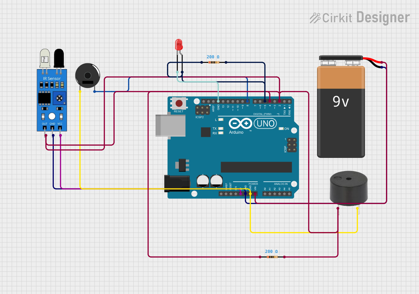
The circuit is designed to interface an IR sensor with an Arduino UNO to detect a certain condition (e.g., presence of an object or a specific signal). Upon detection, the circuit activates a Piezo Buzzer and a red LED as indicators. The circuit is powered by a 9V battery, which is connected to the Arduino's Vin pin for voltage input and GND pin for ground. The IR sensor's output is connected to a digital input pin on the Arduino, and the buzzer and LED are connected to digital output pins. The LED is connected in series with a resistor to limit the current and protect the LED.
Component List
Arduino UNO
- Microcontroller board based on the ATmega328P
- Used as the main controller for the circuit
IR Sensor
- Sensor with digital output to detect certain conditions
- Connected to the Arduino for signal processing
Piezo Buzzer
- An electronic device that emits a tone when voltage is applied
- Used as an audible indicator in the circuit
9V Battery
- Provides power to the circuit
- Connected to the Arduino's Vin and GND pins
Buzzer
- Another audible indicator device
- It is unclear from the parts list why this additional buzzer is included, as there is already a Piezo Buzzer present
LED: Two Pin (red)
- A red light-emitting diode
- Used as a visual indicator in the circuit
Resistor (200 Ohms)
- Two resistors with a resistance of 200 Ohms each
- Used to limit current to the LED and possibly for other signal conditioning purposes
Wiring Details
Arduino UNO
- 5V pin connected to the Vcc pin of the IR sensor
- GND pin connected to the GND pins of the IR sensor, Piezo Buzzer, and the negative terminal of the 9V Battery
- Vin pin connected to the positive terminal of the 9V Battery
- Digital Pin 2 (D2) connected to the output of the IR sensor
- Digital Pin 4 (D4) connected to the IR sensor (purpose unclear without additional context)
- Digital Pin 5 (D5) connected to one end of a 200 Ohm resistor, the other end connected to the anode of the red LED
- Digital Pin 8 (D8) connected to the Piezo Buzzer
- GND pin connected to the cathode of the red LED
IR Sensor
- Vcc pin connected to the 5V pin of the Arduino UNO
- GND pin connected to the GND pin of the Arduino UNO
- Out pin connected to Digital Pin 2 (D2) of the Arduino UNO
Piezo Buzzer
- Pin 1 connected to the GND pin of the Arduino UNO
- Pin 2 connected to Digital Pin 8 (D8) of the Arduino UNO
9V Battery
- "+" terminal connected to the Vin pin of the Arduino UNO
- "-" terminal connected to the GND pin of the Arduino UNO
LED: Two Pin (red)
- Cathode connected to the GND pin of the Arduino UNO
- Anode connected to one end of a 200 Ohm resistor, the other end connected to Digital Pin 5 (D5) of the Arduino UNO
Resistor (200 Ohms)
- One resistor connected between Digital Pin 5 (D5) of the Arduino UNO and the anode of the red LED
- The purpose of the second resistor is unclear without additional context
Documented Code
// sketch.ino

int sensorPin = 2; // IR sensor OUT pin connected to Digital Pin 2
int buzzerPin = 8; // Piezo Buzzer pin connected to Digital Pin 8
int ledPin = 5;    // LED anode connected to Digital Pin 5
int sensorValue = 0; // Variable to store the sensor output

void setup() {
  pinMode(sensorPin, INPUT); // Set the sensor pin as input
  pinMode(buzzerPin, OUTPUT); // Set the buzzer pin as output
  pinMode(ledPin, OUTPUT);    // Set the LED pin as output
}

void loop() {
  sensorValue = digitalRead(sensorPin); // Read the sensor output
  if (sensorValue == HIGH) {
    // If the sensor detects the condition
    digitalWrite(buzzerPin, HIGH); // Turn on the buzzer
    digitalWrite(ledPin, HIGH);    // Turn on the LED
  } else {
    digitalWrite(buzzerPin, LOW); // Turn off the buzzer
    digitalWrite(ledPin, LOW);    // Turn off the LED
  }
}
The code provided is for an Arduino UNO microcontroller. It initializes the IR sensor, Piezo Buzzer, and LED pins, and in the main loop, it reads the sensor output. If the sensor output is HIGH, it activates the buzzer and LED, otherwise, it deactivates them.