
Circuit Documentation
Summary
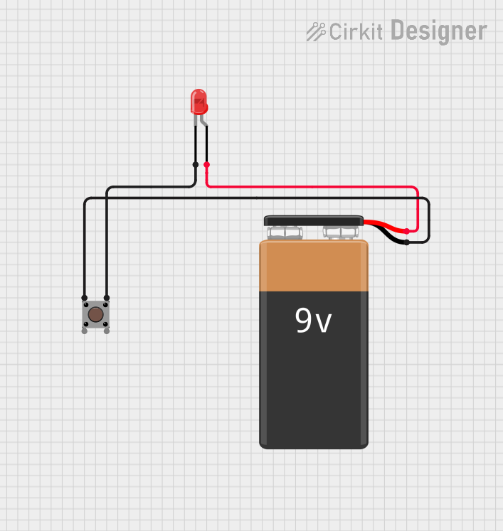
This document provides a detailed description of a simple circuit consisting of a red LED, a pushbutton, and a 9V battery. The circuit is designed to light up the LED when the pushbutton is pressed.
Component List
LED: Two Pin (red)
- Description: A red light-emitting diode (LED) with two pins: anode and cathode.
- Pins:
- Cathode
- Anode
Pushbutton
- Description: A pushbutton switch with four pins: two input pins and two output pins.
- Pins:
- Pin 1 (in)
- Pin 2 (in)
- Pin 3 (out)
- Pin 4 (out)
9V Battery
- Description: A 9V battery with two terminals: positive (+) and negative (-).
- Pins:
- Positive (+)
- Negative (-)
Wiring Details
LED: Two Pin (red)
- Cathode: Connected to Pin 3 (out) of the Pushbutton.
- Anode: Connected to the Positive (+) terminal of the 9V Battery.
Pushbutton
- Pin 1 (in): Connected to the Negative (-) terminal of the 9V Battery.
- Pin 3 (out): Connected to the Cathode of the LED.
9V Battery
- Positive (+): Connected to the Anode of the LED.
- Negative (-): Connected to Pin 1 (in) of the Pushbutton.
Code
There is no microcontroller code associated with this circuit.
This document provides a comprehensive overview of the circuit, including a summary, detailed component descriptions, and wiring details. The circuit is straightforward and does not include any microcontroller code.