
Arduino Nano Controlled Stepper Motor with Rotary Potentiometer Speed Adjustment
View and Edit Project In Cirkit Designer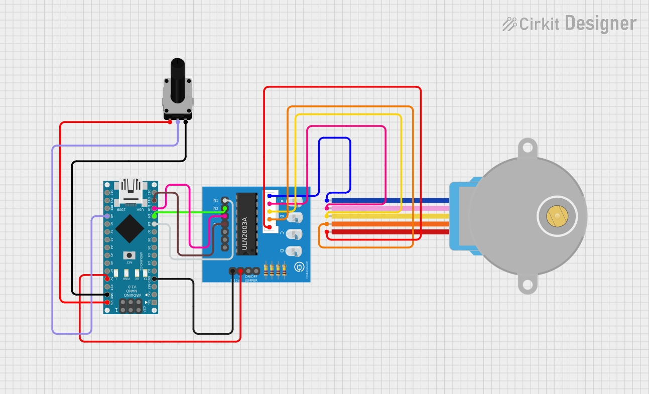
Circuit Documentation
Summary
This circuit consists of an Arduino Nano microcontroller, a ULN2003A breakout board, a 28BYJ-48 stepper motor, and a rotary potentiometer. The Arduino Nano reads the analog value from the potentiometer and controls the stepper motor speed through the ULN2003A driver.
Component List
Arduino Nano
- Description: A small, complete, and breadboard-friendly board based on the ATmega328P.
- Pins: D1/TX, D0/RX, RESET, GND, D2, D3, D4, D5, D6, D7, D8, D9, D10, D11/MOSI, D12/MISO, VIN, 5V, A7, A6, A5, A4, A3, A2, A1, A0, AREF, 3V3, D13/SCK
ULN2003A Breakout Board
- Description: A Darlington transistor array used to drive the stepper motor.
- Pins: In 1, In 2, In 3, In 4, In 5, In 6, In 7, 0V, +5V, ON/OFF jumper switch, BLUE wire, PINK wire, YELLOW wire, ORANGE wire, RED wire
28BYJ-48 Stepper Motor
- Description: A small, inexpensive, and easy-to-use stepper motor.
- Pins: BLUE, PINK, YELLOW, ORANGE, RED
Rotary Potentiometer
- Description: A variable resistor used to provide an analog input to the Arduino.
- Pins: leg1, wiper, leg2
- Properties:
- Resistance: 10,000 Ohms
Wiring Details
Arduino Nano
- GND connected to ULN2003A breakout board 0V
- D8 connected to ULN2003A breakout board In 1
- D9 connected to ULN2003A breakout board In 2
- D10 connected to ULN2003A breakout board In 3
- D11/MOSI connected to ULN2003A breakout board In 4
- VIN connected to Rotary Potentiometer leg1
- GND connected to Rotary Potentiometer leg2
- 5V connected to ULN2003A breakout board +5V
- A0 connected to Rotary Potentiometer wiper
ULN2003A Breakout Board
- 0V connected to Arduino Nano GND
- In 1 connected to Arduino Nano D8
- In 2 connected to Arduino Nano D9
- In 3 connected to Arduino Nano D10
- In 4 connected to Arduino Nano D11/MOSI
- +5V connected to Arduino Nano 5V
- BLUE wire connected to 28BYJ-48 Stepper Motor BLUE
- PINK wire connected to 28BYJ-48 Stepper Motor PINK
- YELLOW wire connected to 28BYJ-48 Stepper Motor YELLOW
- ORANGE wire connected to 28BYJ-48 Stepper Motor ORANGE
- RED wire connected to 28BYJ-48 Stepper Motor RED
28BYJ-48 Stepper Motor
- BLUE connected to ULN2003A breakout board BLUE wire
- PINK connected to ULN2003A breakout board PINK wire
- YELLOW connected to ULN2003A breakout board YELLOW wire
- ORANGE connected to ULN2003A breakout board ORANGE wire
- RED connected to ULN2003A breakout board RED wire
Rotary Potentiometer
- leg1 connected to Arduino Nano VIN
- wiper connected to Arduino Nano A0
- leg2 connected to Arduino Nano GND
Code Documentation
Arduino Nano Code
#include <Stepper.h>

const int stepsPerRevolution = 200;
Stepper myStepper(stepsPerRevolution, 4, 5, 6, 7);
int stepCount = 0;

void setup() {
}

void loop() {
   int sensorReading = analogRead(A0);
   int motorSpeed = map(sensorReading, 0, 1023, 0, 100);
   if (motorSpeed > 0) {
    myStepper.setSpeed(motorSpeed);
    myStepper.step(stepsPerRevolution / 100);
  }
}
This code initializes a stepper motor with 200 steps per revolution. In the loop function, it reads the analog value from pin A0 (connected to the potentiometer), maps this value to a motor speed, and if the speed is greater than 0, it sets the motor speed and steps the motor.