Arduino UNO-Based Battery-Powered Robotic Car with Motor Control
Circuit Documentation
Summary
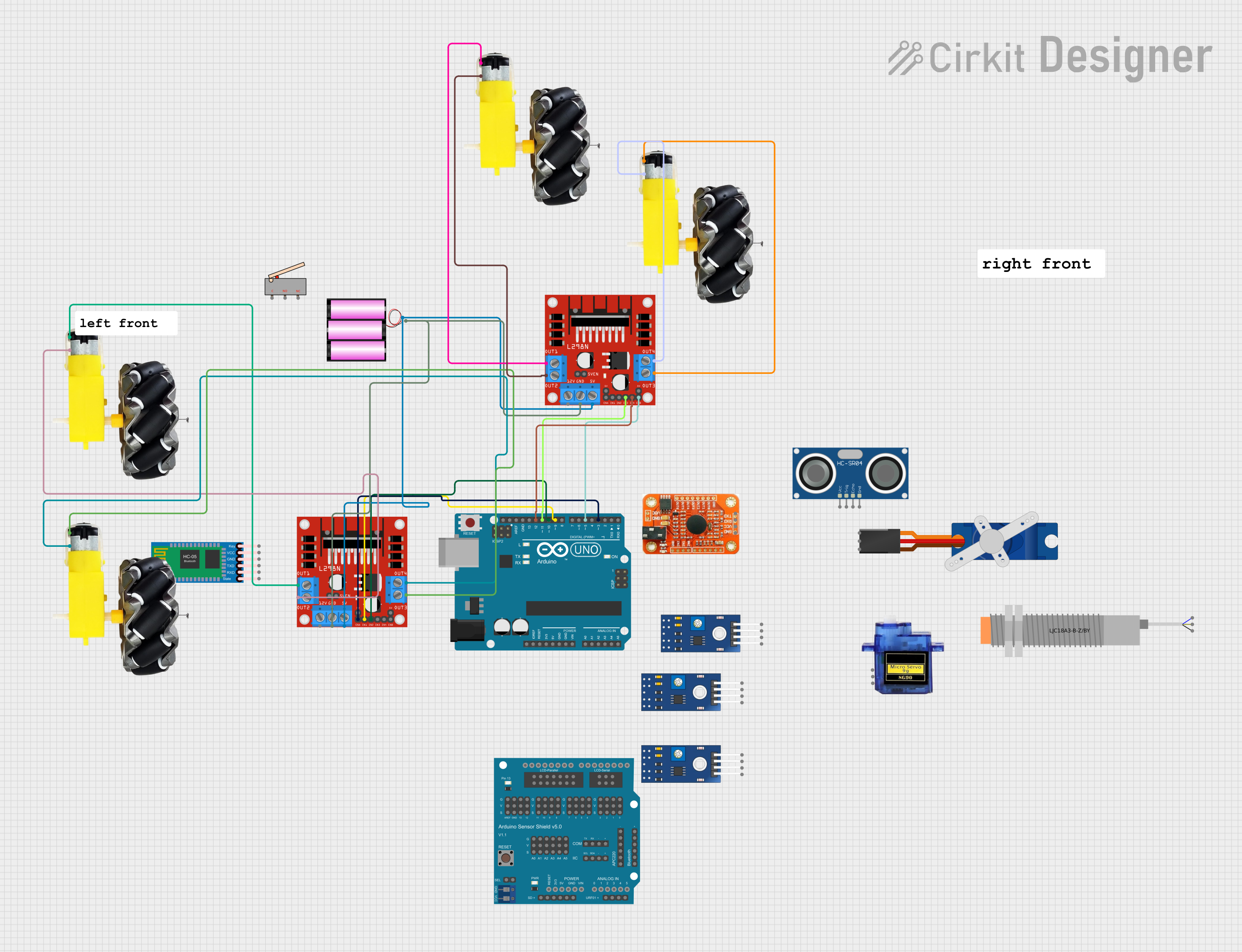
This document provides a detailed overview of a circuit that includes an Arduino UNO microcontroller, motor drivers, motors, sensors, and other components. The circuit is designed to control multiple motors and sensors, with the Arduino UNO serving as the central control unit. The document includes a component list, wiring details, and the code used in the microcontroller.
Component List
Arduino UNO
- Description: A microcontroller board based on the ATmega328P.
- Pins: UNUSED, IOREF, Reset, 3.3V, 5V, GND, Vin, A0, A1, A2, A3, A4, A5, SCL, SDA, AREF, D13, D12, D11, D10, D9, D8, D7, D6, D5, D4, D3, D2, D1, D0
Micro servo 9G
- Description: A small servo motor used for precise control of angular position.
- Pins: GND, +5V, PWM
HC-SR04 Ultrasonic Sensor
- Description: A sensor used for distance measurement.
- Pins: VCC, TRIG, ECHO, GND
TCRT 5000 IR SENSOR
- Description: An infrared sensor used for object detection.
- Pins: VCC, GND, DO, AO
HC-05 Bluetooth Module
- Description: A Bluetooth module used for wireless communication.
- Pins: Key, VCC, GND, TXD, RXD, State
L298N DC motor driver
- Description: A dual H-bridge motor driver used to control the speed and direction of DC motors.
- Pins: OUT1, OUT2, 12V, GND, 5V, OUT3, OUT4, 5V-ENA-JMP-I, 5V-ENA-JMP-O, +5V-J1, +5V-J2, ENA, IN1, IN2, IN3, IN4, ENB
LJC18A3-B-Z/BY Capacitive Proximity Sensor
- Description: A capacitive sensor used for proximity detection.
- Pins: VO (BLU), VI (BRN), SIG (BLK)
Limit switch
- Description: A switch used to detect the presence or absence of an object.
- Pins: C, NO, NC
Voice recognition module
- Description: A module used for recognizing voice commands.
- Pins: GND, VCC, RDX, RTX
Motor and wheels
- Description: A motor with attached wheels used for movement.
- Pins: vcc, GND
Tower Pro SG90 servo
- Description: A small servo motor used for precise control of angular position.
- Pins: Signal, +5V, GND
Arduino Sensor Shield v5.0
- Description: A shield that provides easy connections for sensors and actuators.
- Pins: VCC, SD-VCC, SD-GND, SD-D11, SD-D10, SD-D13, SD-D12, URF01-VCC, URF01-A0, URF01-A1, URF01-GND, GND, SEL1, SEL2, A0-SIG, A0-VCC, A0-GND, A1-SIG, A1-VCC, A1-GND, A2-SIG, A2-VCC, A2-GND, A3-SIG, A3-VCC, A3-GND, A4-SIG, A4-VCC, A4-GND, A5-SIG, A5-VCC, A5-GND, IIC-SCL, IIC-SDA, IIC-GND, IIC-VCC, COM-TX, COM-RX, COM-GND, COM-VCC, APC220-, APC220-D0, APC220-D1, APC220-VCC, APC220-GND, BLUETOOTH-3V3, BLUETOOTH-GND, BLUETOOTH-D0, BLUETOOTH-D1, BLUETOOTH-VCC, AREF-S, AREF-V, AREF-G, GND-S, GND-V, GND-G, 13-S, 13-V, 13-G, 12-S, 12-V, 12-G, 11-S, 11-V, 11-G, 10-S, 10-V, 10-G, 9-S, 9-V, 9-G, 8-S, 8-V, 8-G, 7-S, 7-V, 7-G, 6-S, 6-V, 6-G, 5-S, 5-V, 5-G, 4-S, 4-V, 4-G, 3-S, 3-V, 3-G, 2-S, 2-V, 2-G, 1-S, 1-V, 1-G, 0-S, 0-V, 0-G, ParallelLCD-VCC, ParallelLCD-D13, ParallelLCD-GND, ParallelLCD-D12, ParallelLCD-D2, ParallelLCD-D11, ParallelLCD-D3, ParallelLCD-D10, ParallelLCD-D4, ParallelLCD-D9, ParallelLCD-D5, ParallelLCD-D8, ParallelLCD-D6, ParallelLCD-D7, SerialLCD-D4, SerialLCD-VCC, SerialLCD-D3, SerialLCD-, SerialLCD-D2, SerialLCD-GND
Battery 12V
- Description: A 12V battery used to power the circuit.
- Pins: +, -
Comment
- Description: A placeholder for comments in the circuit.
- Pins: None
Wiring Details
Arduino UNO
- D12 connected to L298N DC motor driver (IN4)
- D11 connected to L298N DC motor driver (IN3)
- D10 connected to L298N DC motor driver (IN2)
- D9 connected to L298N DC motor driver (IN1)
- D5 connected to L298N DC motor driver (ENB)
- D3 connected to L298N DC motor driver (ENA)
L298N DC motor driver
- IN4 connected to Arduino UNO (D12)
- IN3 connected to Arduino UNO (D11)
- IN2 connected to Arduino UNO (D10)
- IN1 connected to Arduino UNO (D9)
- ENB connected to Arduino UNO (D5)
- ENA connected to Arduino UNO (D3)
- OUT1 connected to Motor and wheels (vcc)
- OUT2 connected to Motor and wheels (GND)
- OUT3 connected to Motor and wheels (vcc)
- OUT4 connected to Motor and wheels (GND)
- GND connected to Battery 12V (-)
- 5V connected to Battery 12V (+)
Motor and wheels
- vcc connected to L298N DC motor driver (OUT1)
- GND connected to L298N DC motor driver (OUT2)
- vcc connected to L298N DC motor driver (OUT3)
- GND connected to L298N DC motor driver (OUT4)
Battery 12V
- - connected to L298N DC motor driver (GND)
- + connected to L298N DC motor driver (5V)
Code
Arduino UNO Code (sketch.ino)
void setup() {
  // put your setup code here, to run once:

}

void loop() {
  // put your main code here, to run repeatedly:

}
Documentation (documentation.txt)
This document provides a comprehensive overview of the circuit, including the components used, their wiring details, and the code for the Arduino UNO microcontroller.