
Arduino UNO-Based Environmental Monitoring System with Soil Moisture, Temperature, Humidity, and Light Sensors
View and Edit Project In Cirkit Designer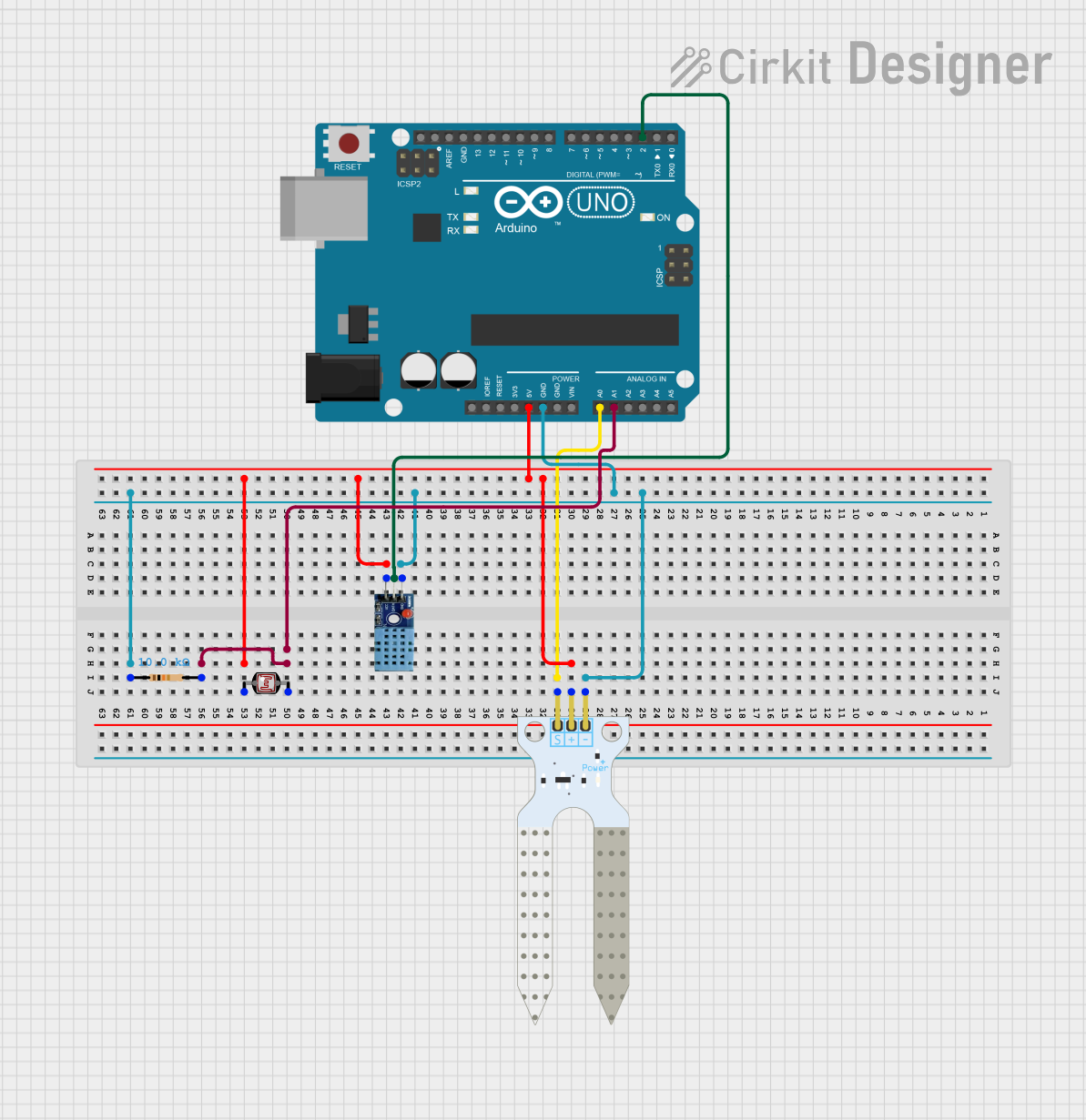
Circuit Documentation
Summary
This circuit is designed to read data from a soil moisture sensor, a DHT11 temperature and humidity sensor, and a photocell (LDR). The sensor readings are then displayed on the Serial Monitor using an Arduino UNO microcontroller.
Component List
Arduino UNO
- Description: A microcontroller board based on the ATmega328P.
- Pins: UNUSED, IOREF, Reset, 3.3V, 5V, GND, Vin, A0, A1, A2, A3, A4, A5, SCL, SDA, AREF, D13, D12, D11, D10, D9, D8, D7, D6, D5, D4, D3, D2, D1, D0
Soil Moisture Sensor
- Description: A sensor used to measure the moisture level in the soil.
- Pins: VCC, GND, SIG
DHT11
- Description: A sensor used to measure temperature and humidity.
- Pins: VCC, GND, DATA
Photocell (LDR)
- Description: A light-dependent resistor used to measure light levels.
- Pins: pin 0, pin 1
Resistor
- Description: A 10k Ohm resistor used in the circuit.
- Pins: pin1, pin2
- Properties: Resistance = 10k Ohms
Wiring Details
Arduino UNO
- GND: Connected to GND of Soil Moisture Sensor, DHT11, and pin1 of Resistor.
- 5V: Connected to VCC of Soil Moisture Sensor, DHT11, and pin 0 of Photocell (LDR).
- A0: Connected to SIG of Soil Moisture Sensor.
- A1: Connected to pin 1 of Photocell (LDR) and pin2 of Resistor.
- D2: Connected to DATA of DHT11.
Soil Moisture Sensor
- GND: Connected to GND of Arduino UNO.
- VCC: Connected to 5V of Arduino UNO.
- SIG: Connected to A0 of Arduino UNO.
DHT11
- GND: Connected to GND of Arduino UNO.
- VCC: Connected to 5V of Arduino UNO.
- DATA: Connected to D2 of Arduino UNO.
Photocell (LDR)
- pin 0: Connected to 5V of Arduino UNO.
- pin 1: Connected to A1 of Arduino UNO and pin2 of Resistor.
Resistor
- pin1: Connected to GND of Arduino UNO.
- pin2: Connected to pin 1 of Photocell (LDR) and A1 of Arduino UNO.
Code Documentation
/*
 * This Arduino Sketch reads data from a soil moisture sensor, a DHT11 sensor,
 * and a photocell (LDR). It then displays the sensor readings on the Serial
 * Monitor.
 */

#include <DHT.h>

// Pin definitions
#define SOIL_MOISTURE_PIN A0
#define DHT_PIN 2
#define LDR_PIN A1
#define DHT_TYPE DHT11

DHT dht(DHT_PIN, DHT_TYPE);

void setup() {
  // Initialize Serial Monitor
  Serial.begin(9600);
  Serial.println("Initializing...");

  // Initialize the DHT sensor
  dht.begin();

  // Wait for sensors to stabilize
  delay(2000);
}

void loop() {
  // Read soil moisture
  int soilMoistureValue = analogRead(SOIL_MOISTURE_PIN);

  // Read temperature and humidity from DHT11
  float humidity = dht.readHumidity();
  float temperature = dht.readTemperature();

  // Read light level from LDR
  int ldrValue = analogRead(LDR_PIN);

  // Display soil moisture
  Serial.print("Soil Moisture: ");
  Serial.println(soilMoistureValue);

  // Display temperature and humidity
  Serial.print("Temperature: ");
  Serial.print(temperature);
  Serial.println(" C");
  Serial.print("Humidity: ");
  Serial.print(humidity);
  Serial.println(" %");

  // Display light level
  Serial.print("Light Level: ");
  Serial.println(ldrValue);

  // Wait before next update
  delay(2000);
}
This code initializes the sensors and reads data from the soil moisture sensor, DHT11 sensor, and photocell (LDR). The readings are then displayed on the Serial Monitor every 2 seconds.