
Arduino and ESP32-CAM Controlled Multi-Motor System with Wireless Communication and Color Sensing
View and Edit Project In Cirkit Designer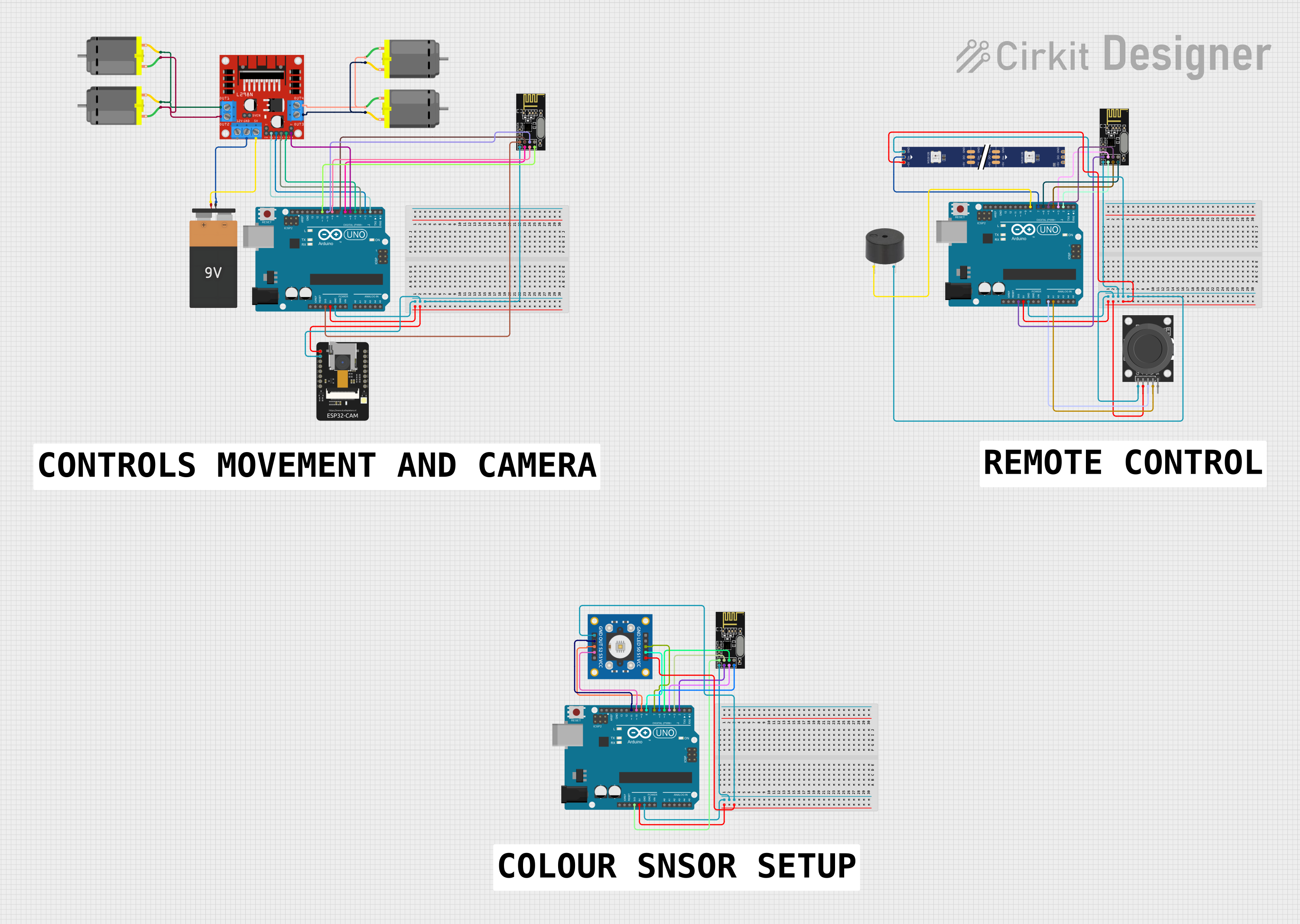
Circuit Documentation
Summary
This circuit integrates various components including microcontrollers, sensors, a motor driver, DC motors, a wireless communication module, an LED strip, and a buzzer. The primary microcontrollers used are Arduino UNOs and an ESP32-CAM. The circuit features motor control via the L298N motor driver, wireless communication through NRF24L01 modules, color sensing with a TCS3200 color sensor, and user input through a KY-023 Dual Axis Joystick. Additionally, visual feedback is provided by a WS2812 RGB LED strip, and auditory feedback is given by a buzzer.
Component List
- Arduino UNO: A microcontroller board based on the ATmega328P, featuring digital and analog I/O pins.
- DC Motor: An electric motor that runs on direct current (DC) electricity.
- L298N DC Motor Driver: A module that allows control of two DC motors or one stepper motor.
- Battery 9V: A standard 9V battery providing power to the circuit.
- ESP32-CAM: A small camera module with Wi-Fi capabilities.
- NRF24L01: A 2.4GHz wireless transceiver module for communication between devices.
- KY-023 Dual Axis Joystick Module: A joystick providing two-axis control and a pushbutton switch.
- TCS3200 Color Sensor: A sensor that detects color and provides a frequency output corresponding to the color.
- WS2812 RGB LED Strip: An addressable LED strip that can display multiple colors.
- Buzzer: An electronic component that emits sound.
Wiring Details
Arduino UNO
- 5V: Powers the ESP32-CAM and the KY-023 Joystick Module.
- GND: Common ground for ESP32-CAM, NRF24L01 modules, KY-023 Joystick Module, WS2812 RGB LED strip, and buzzer.
- 3.3V: Powers the NRF24L01 modules and the TCS3200 color sensor.
- Digital Pins (D2-D13): Control signals for the L298N motor driver, NRF24L01 modules, WS2812 RGB LED strip, buzzer, and TCS3200 color sensor.
- Analog Pins (A0-A1): Analog inputs from the KY-023 Joystick Module.
DC Motor
- Pin 1 & Pin 2: Connected to the L298N motor driver outputs to control motor rotation.
L298N DC Motor Driver
- OUT1-OUT4: Outputs to DC motors.
- GND: Ground connection.
- 5V: Powered by the 9V battery.
- ENA, ENB, IN1-IN4: Control signals from the Arduino UNO for motor operation.
Battery 9V
- VCC: Supplies power to the L298N motor driver.
- GND: Ground connection.
ESP32-CAM
- 5V: Powered by the Arduino UNO.
- GND: Ground connection.
NRF24L01
- VCC (3V): Powered by the Arduino UNO's 3.3V output.
- GND: Ground connection.
- CE, CSN, SCK, MOSI, MISO: SPI communication with the Arduino UNO.
KY-023 Dual Axis Joystick Module
- +5V: Powered by the Arduino UNO.
- GND: Ground connection.
- VRx, VRy: Analog outputs to the Arduino UNO's analog inputs.
TCS3200 Color Sensor
- VCC: Powered by the Arduino UNO's 5V output.
- GND: Ground connection.
- OUT, S0-S3: Output and control signals to the Arduino UNO.
WS2812 RGB LED Strip
- 5V: Powered by the Arduino UNO.
- GND: Ground connection.
- DIN: Data input from the Arduino UNO.
Buzzer
- PIN: Control signal from the Arduino UNO.
- GND: Ground connection.
Documented Code
Arduino UNO (Primary Controller)
void setup() {
  // put your setup code here, to run once:

}

void loop() {
  // put your main code here, to run repeatedly:

}
Arduino UNO (Joystick and LED Controller)
void setup() {
  // put your setup code here, to run once:

}

void loop() {
  // put your main code here, to run repeatedly:

}
Arduino UNO (Color Sensor Controller)
void setup() {
  // put your setup code here, to run once:

}

void loop() {
  // put your main code here, to run repeatedly:

}
This documentation provides an overview of the circuit's components, their wiring, and the placeholder code for the microcontrollers. The actual functionality will be defined within the code, which is currently not provided in detail.