
Raspberry Pi 3B-Based Multi-Sensor Distance Measurement System
View and Edit Project In Cirkit Designer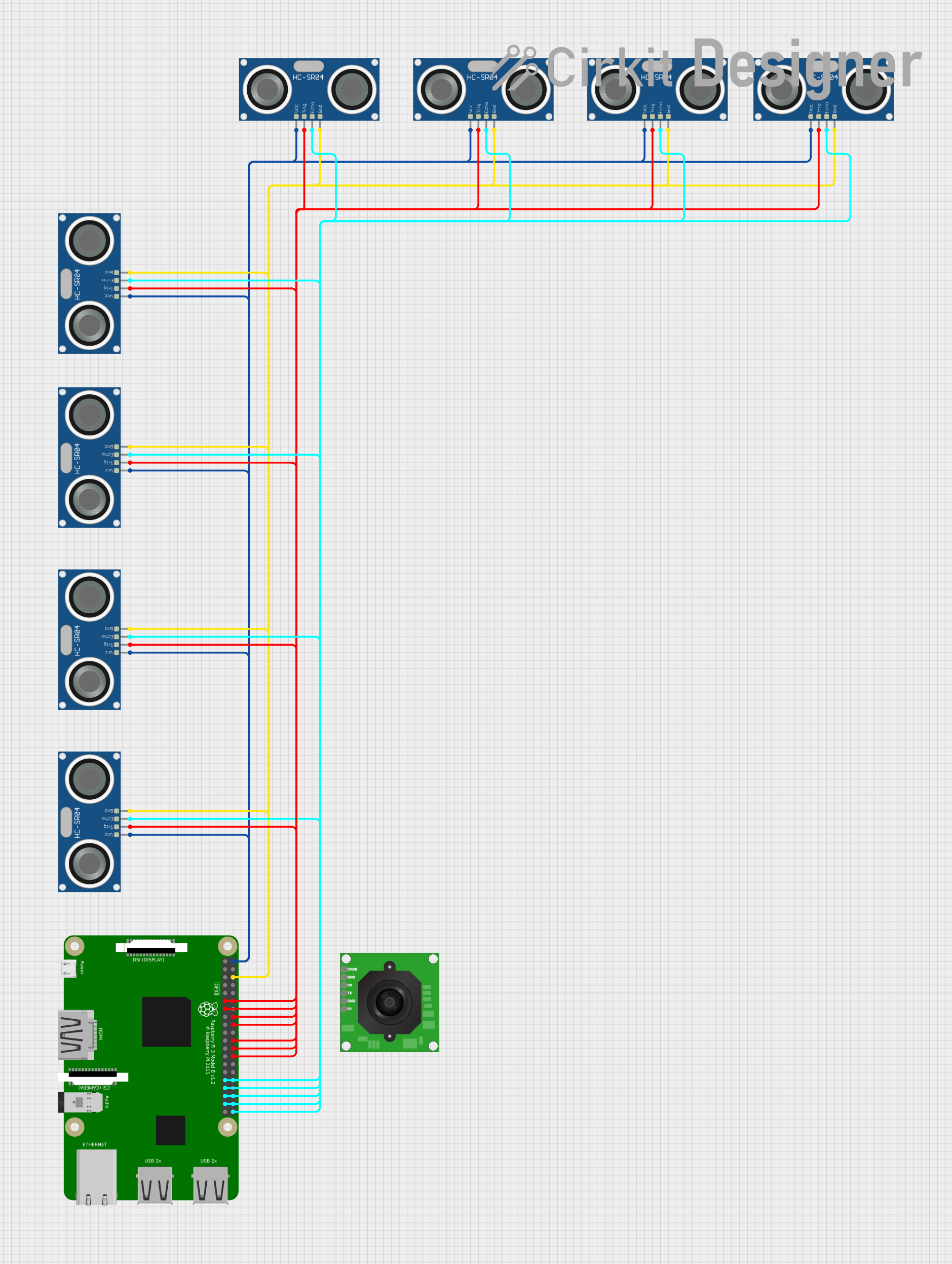
Circuit Documentation
Summary
This circuit integrates a Raspberry Pi 3B with multiple HC-SR04 Ultrasonic Sensors and a TTL Serial JPEG Camera. The Raspberry Pi 3B serves as the central processing unit, controlling the ultrasonic sensors to measure distances and interfacing with the camera for image capture. The ultrasonic sensors are connected to the Raspberry Pi's GPIO pins, with separate pins for trigger and echo functions. The camera is connected via serial communication to the Raspberry Pi. The circuit is powered by the Raspberry Pi's 5V supply, which is distributed to the ultrasonic sensors.
Component List
Raspberry Pi 3B
- Description: A single-board computer with GPIO capabilities.
- Pins: 3v3, GPIO2, GPIO3, GPIO4, GND, GPIO17, GPIO27, GPIO22, 3V3, GPIO10, GPIO9, GPIO11, ID_SD, GPIO5, GPIO6, GPIO13, GPIO19, GPIO26, GPIO21, GPIO20, GPIO16, GPIO12, ID_SC, GPIO7, GPIO8, GPIO25, GPIO24, GPIO23, GPIO18, GPIO15, GPIO14, 5V.
HC-SR04 Ultrasonic Sensor
- Description: An ultrasonic distance sensor.
- Pins: VCC, TRIG, ECHO, GND.
TTL Serial JPEG Camera
- Description: A camera module with serial communication.
- Pins: GND, RX, TX, CVBS, 5V.
Wiring Details
Raspberry Pi 3B
- GPIO17: Connected to TRIG of one HC-SR04 Ultrasonic Sensor.
- GPIO27, GPIO22, GPIO10, GPIO9, GPIO11, GPIO5, GPIO13, GPIO19, GPIO26, GPIO21, GPIO20, GPIO16, GPIO12, GPIO7, GPIO8, GPIO25, GPIO24, GPIO23, GPIO18: Connected to TRIG and ECHO of various HC-SR04 Ultrasonic Sensors.
- GND: Common ground with all HC-SR04 Ultrasonic Sensors and TTL Serial JPEG Camera.
- 5V: Power supply for all HC-SR04 Ultrasonic Sensors.
HC-SR04 Ultrasonic Sensors
- VCC: Connected to the 5V pin of the Raspberry Pi 3B.
- TRIG: Connected to specific GPIO pins on the Raspberry Pi 3B for triggering the distance measurement.
- ECHO: Connected to specific GPIO pins on the Raspberry Pi 3B to receive the distance measurement.
- GND: Common ground with the Raspberry Pi 3B.
TTL Serial JPEG Camera
- GND: Connected to the common ground on the Raspberry Pi 3B.
- RX: To be connected to a TX pin on the Raspberry Pi 3B for serial communication.
- TX: To be connected to an RX pin on the Raspberry Pi 3B for serial communication.
- CVBS: Composite video broadcasting signal (not connected in this setup).
- 5V: Power supply from the Raspberry Pi 3B.
Documented Code
No code has been provided for the microcontrollers in the circuit. The code would typically include initialization of GPIO pins, serial communication setup, and logic for triggering the ultrasonic sensors and capturing data from the camera. It would also handle the processing of sensor data and possibly include image processing or storage functions for the camera module.