
Arduino UNO R4 WiFi-Based Smart Lock System with RFID and Motion Detection
View and Edit Project In Cirkit Designer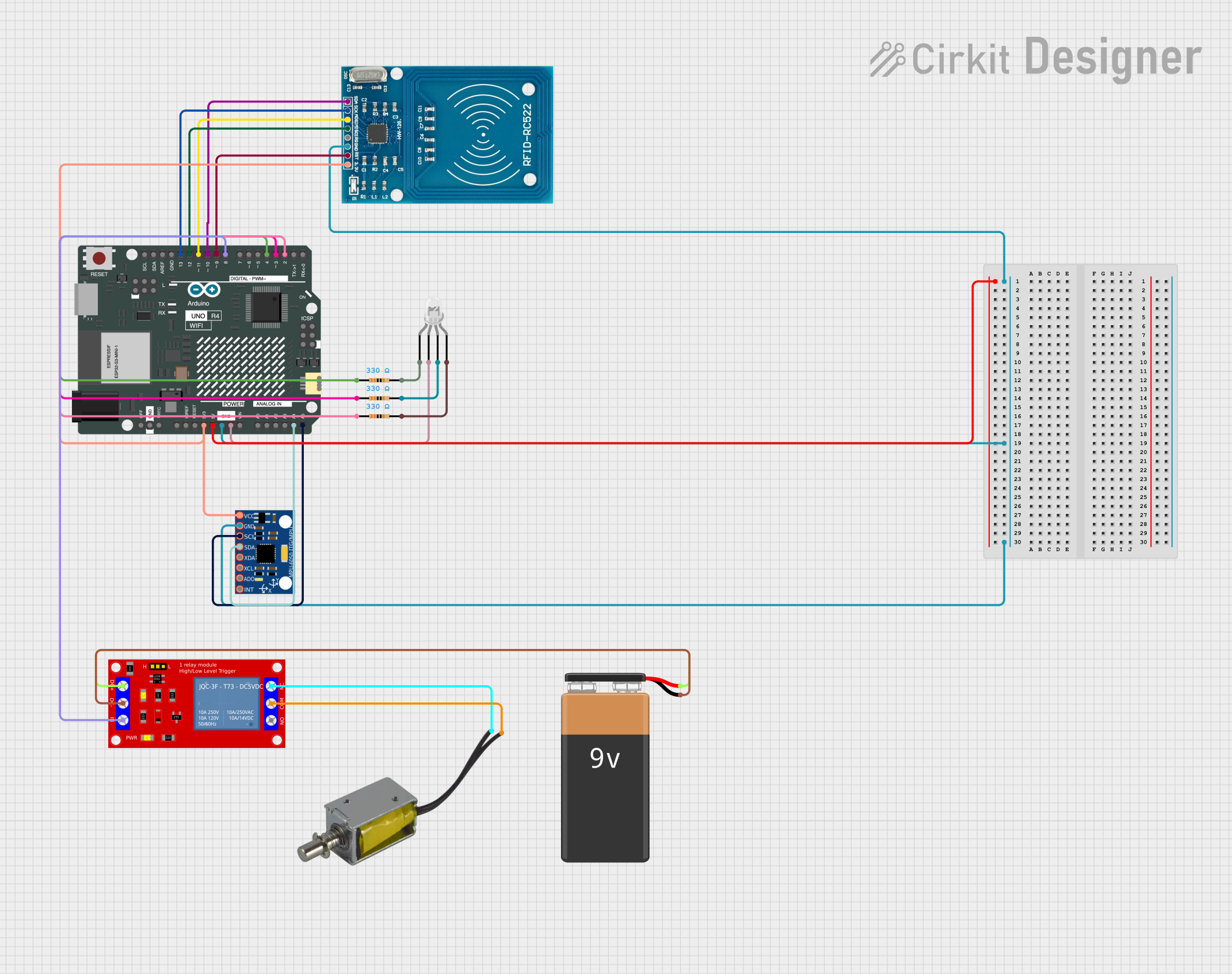
Circuit Documentation
Summary
This document provides a detailed overview of a circuit that integrates an Arduino UNO R4 WiFi microcontroller with various sensors and actuators. The circuit includes an RFID reader, an MPU-6050 accelerometer and gyroscope, a push-pull solenoid, a 9V battery, a four-pin LED, resistors, and a 1-channel 5V relay module. The Arduino UNO R4 WiFi is programmed to control these components, enabling functionalities such as RFID-based access control and motion detection.
Component List
Arduino UNO R4 WiFi
- Description: A microcontroller board based on the ATmega328P, featuring built-in WiFi capabilities.
- Pins: OFF, GND, VRTC, IIC0_SCL, IIC0_SDA, 3V3, GPIO 41, GPIO 0, GPIO 42, GPIO 43, GPIO 44, BOOT, IOREF, RESET, 5V, VIN, A0, A1, A2, A3, A4, A5, RSPCKA, CIPO, COPI, D0/RX, D1/TX, D2, D3, D4, D5, D6, D7, D8, D9, D10, D11, D12, D13, AREF, SDA, SCL
RFID-RC522
- Description: An RFID reader module used for reading RFID tags.
- Pins: VCC (3.3V), RST, GND, IRQ, MISO, MOSI, SCK, SDA
MPU-6050
- Description: A 6-axis motion tracking device that includes a 3-axis gyroscope and a 3-axis accelerometer.
- Pins: VCC, GND, SCL, SDA, XDA, XCL, AD0, INT
Push Pull Solenoid
- Description: An electromechanical device used to push or pull when activated.
- Pins: +ve, -ve
9V Battery
- Description: A power source providing 9V DC.
- Pins: -, +
LED: Four Pin
- Description: A four-pin LED with separate cathodes for red, green, and blue, and a common anode.
- Pins: red cathode, common anode, green cathode, blue cathode
Resistor (330 Ohms)
- Description: A resistor with a resistance of 330 Ohms.
- Pins: pin1, pin2
1 Channel 5V Relay Module
- Description: A relay module used to control high voltage devices with a low voltage signal.
- Pins: VCC+, VCC- (GND), IN, N.O., COM, N.C.
Wiring Details
Arduino UNO R4 WiFi
- 3V3 connected to VCC (3.3V) of RFID-RC522 and VCC of MPU-6050.
- GND connected to GND of RFID-RC522, GND of MPU-6050, and common anode of LED.
- A4 connected to SDA of MPU-6050.
- A5 connected to SCL of MPU-6050.
- D2 connected to pin1 of a 330 Ohm resistor.
- D3 connected to pin1 of another 330 Ohm resistor.
- D4 connected to pin1 of another 330 Ohm resistor.
- D8 connected to IN of the 1 Channel 5V Relay Module.
- D9 connected to RST of RFID-RC522.
- D10 connected to SDA of RFID-RC522.
- D11 connected to MOSI of RFID-RC522.
- D12 connected to MISO of RFID-RC522.
- D13 connected to SCK of RFID-RC522.
RFID-RC522
- VCC (3.3V) connected to 3V3 of Arduino UNO R4 WiFi.
- GND connected to GND of Arduino UNO R4 WiFi.
- RST connected to D9 of Arduino UNO R4 WiFi.
- SDA connected to D10 of Arduino UNO R4 WiFi.
- MOSI connected to D11 of Arduino UNO R4 WiFi.
- MISO connected to D12 of Arduino UNO R4 WiFi.
- SCK connected to D13 of Arduino UNO R4 WiFi.
MPU-6050
- VCC connected to 3V3 of Arduino UNO R4 WiFi.
- GND connected to GND of Arduino UNO R4 WiFi.
- SDA connected to A4 of Arduino UNO R4 WiFi.
- SCL connected to A5 of Arduino UNO R4 WiFi.
Push Pull Solenoid
- +ve connected to N.C. of 1 Channel 5V Relay Module.
- -ve connected to COM of 1 Channel 5V Relay Module.
9V Battery
- - connected to VCC- (GND) of 1 Channel 5V Relay Module.
- + connected to VCC+ of 1 Channel 5V Relay Module.
LED: Four Pin
- common anode connected to GND of Arduino UNO R4 WiFi.
- red cathode connected to pin2 of a 330 Ohm resistor.
- green cathode connected to pin2 of another 330 Ohm resistor.
- blue cathode connected to pin2 of another 330 Ohm resistor.
Resistors (330 Ohms)
- pin1 of one resistor connected to D2 of Arduino UNO R4 WiFi.
- pin2 of the same resistor connected to red cathode of LED.
- pin1 of another resistor connected to D3 of Arduino UNO R4 WiFi.
- pin2 of the same resistor connected to green cathode of LED.
- pin1 of another resistor connected to D4 of Arduino UNO R4 WiFi.
- pin2 of the same resistor connected to blue cathode of LED.
1 Channel 5V Relay Module
- IN connected to D8 of Arduino UNO R4 WiFi.
- N.C. connected to +ve of Push Pull Solenoid.
- COM connected to -ve of Push Pull Solenoid.
- VCC- (GND) connected to - of 9V Battery.
- VCC+ connected to + of 9V Battery.
Code Documentation
#define BLYNK_TEMPLATE_ID "TMPL2Gs1tAZOJ"
#define BLYNK_TEMPLATE_NAME "Pave"
#define BLYNK_AUTH_TOKEN "FdVKB9c2zOUlEW3MLIxDQHp-sebYt-jO"

#include <cstdlib>
#include <SPI.h>
#include <MFRC522.h>

#define SS_PIN 10
#define RST_PIN 9
MFRC522 mfrc522(SS_PIN, RST_PIN);   // Create MFRC522 instance.
#include <Adafruit_MPU6050.h>
#include <Adafruit_Sensor.h>
#include <Wire.h>
#include <BlynkSimpleWifi.h>

Adafruit_MPU6050 mpu;

int redpin = 4;
int bluepin = 2;
int greenpin = 3;

int pistonpin = 8;

int pos = 0;    // variable to store the servo position

char ssid[] = "Galaxy S22 ADFA";
char password[] = "y&b072224";

void setup()
{
  Blynk.begin(BLYNK_AUTH_TOKEN, ssid, password);
  pinMode(redpin, OUTPUT);
  pinMode(bluepin, OUTPUT);
  pinMode(greenpin, OUTPUT);
  pinMode(pistonpin, OUTPUT);

  Serial.begin(115200);   // Initiate a serial communication
  SPI.begin();      // Initiate  SPI bus
  mfrc522.PCD_Init();   // Initiate MFRC522

  digitalWrite(pistonpin, LOW);

  Serial.println("Approximate your card to the reader...");
  Serial.println();

  while (!Serial) {
    delay(10);
  }

  if (!mpu.begin()) {
    Serial.println("Failed to find MPU6050 chip");
    while (1) {
      delay(10);
    }
  }

  mpu.setAccelerometerRange(MPU6050_RANGE_16_G);
  mpu.setGyroRange(MPU6050_RANGE_250_DEG);
  mpu.setFilterBandwidth(MPU6050_BAND_21_HZ);
  delay(100);
}