
Wi-Fi Controlled Smart Home Automation System with ESP8266 and DHT11
View and Edit Project In Cirkit Designer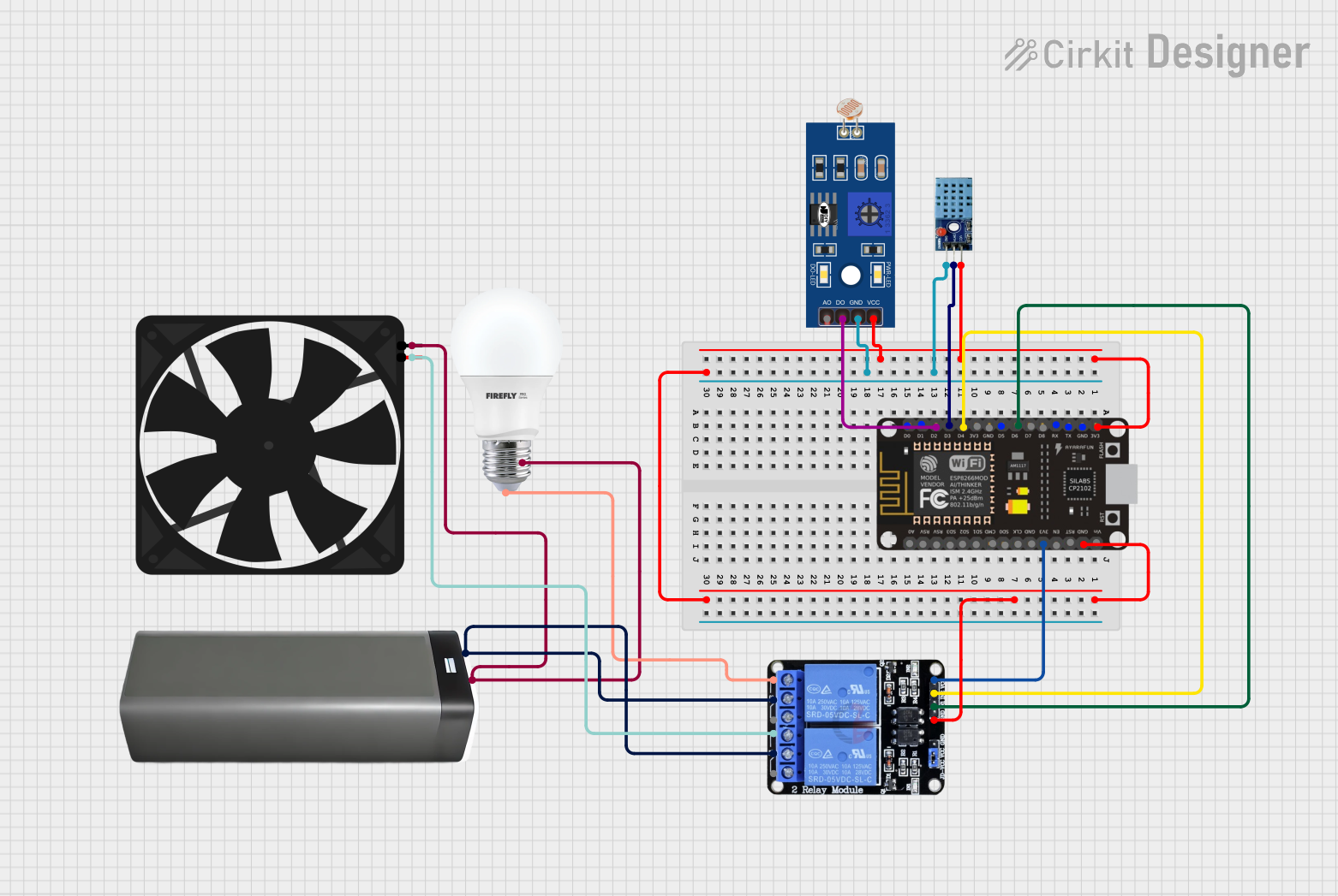
Circuit Documentation
Summary
This document provides a detailed overview of a circuit that includes a DHT11 temperature and humidity sensor, an ESP8266 NodeMCU microcontroller, an LDR (Light Dependent Resistor), a bulb, a battery pack, a fan, and a two-channel relay module. The circuit is designed to monitor environmental conditions and control the bulb and fan based on sensor inputs.
Component List
DHT11 Temperature and Humidity Sensor
- Pins: VCC, GND, DATA
- Description: Measures temperature and humidity.
- Purpose in Circuit: Provides environmental data to the microcontroller.
ESP8266 NodeMCU
- Pins: D0, D1, D2, D3, D4, 3V3, GND, D5, D6, D7, D8, RX, TX, A0, RSV, SD3, SD2, SD1, CMD, SD0, CLK, EN, RST, VIN
- Description: Wi-Fi enabled microcontroller.
- Purpose in Circuit: Central control unit for processing sensor data and controlling the relay module.
LDR (Light Dependent Resistor)
- Pins: A0, D0, GND, VCC
- Description: Measures ambient light levels.
- Purpose in Circuit: Provides light level data to the microcontroller.
Bulb
- Pins: +, -
- Description: Light source.
- Purpose in Circuit: Controlled by the relay module to turn on/off based on sensor data.
Battery Pack
- Pins: +, -
- Description: Power source.
- Purpose in Circuit: Provides power to the fan and bulb.
Fan
- Pins: GND, 5V
- Description: Cooling device.
- Purpose in Circuit: Controlled by the relay module to turn on/off based on sensor data.
Two Channel Relay 5V
- Pins: VCC, IN2, IN1, GND, NC2, C2, NO2, NC1, C1, NO1
- Description: Relay module for controlling high-power devices.
- Purpose in Circuit: Controls the bulb and fan based on signals from the microcontroller.
Wiring Details
DHT11 Temperature and Humidity Sensor
- VCC: Connected to 3V3 of ESP8266 NodeMCU
- GND: Connected to GND of ESP8266 NodeMCU
- DATA: Connected to D3 of ESP8266 NodeMCU
ESP8266 NodeMCU
- 3V3: Connected to VCC of DHT11 and VCC of LDR
- GND: Connected to GND of DHT11, GND of LDR, and GND of Two Channel Relay 5V
- D2: Connected to D0 of LDR
- D3: Connected to DATA of DHT11
- D4: Connected to IN2 of Two Channel Relay 5V
- D6: Connected to IN1 of Two Channel Relay 5V
LDR (Light Dependent Resistor)
- VCC: Connected to 3V3 of ESP8266 NodeMCU
- GND: Connected to GND of ESP8266 NodeMCU
- D0: Connected to D2 of ESP8266 NodeMCU
Bulb
- +: Connected to NC2 of Two Channel Relay 5V
- -: Connected to - of Battery Pack
Battery Pack
- +: Connected to C2 and C1 of Two Channel Relay 5V
- -: Connected to GND of Fan and - of Bulb
Fan
- 5V: Connected to NC1 of Two Channel Relay 5V
- GND: Connected to - of Battery Pack
Two Channel Relay 5V
- VCC: Connected to 3V3 of ESP8266 NodeMCU
- GND: Connected to GND of ESP8266 NodeMCU
- IN2: Connected to D4 of ESP8266 NodeMCU
- IN1: Connected to D6 of ESP8266 NodeMCU
- NC2: Connected to + of Bulb
- C2: Connected to + of Battery Pack
- NC1: Connected to 5V of Fan
- C1: Connected to + of Battery Pack
Code
No code is provided for this circuit.