Cirkit Designer
Your all-in-one circuit design IDE
Home /
Project Documentation
Arduino-Controlled Dual Motor System with IR Sensor Feedback
Circuit Documentation
Summary
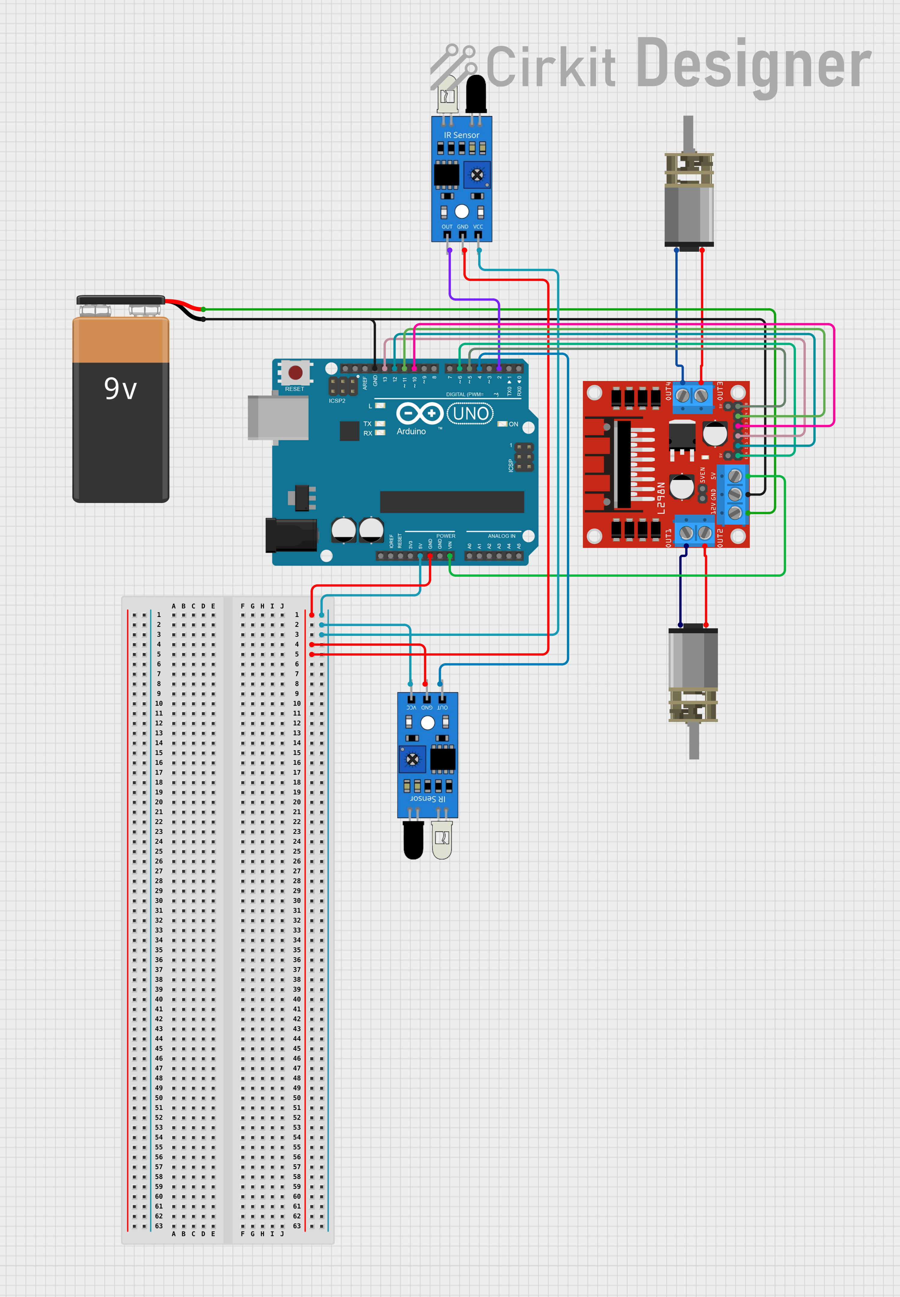
This circuit is designed to control two DC motors using an Arduino UNO as the main microcontroller and an L298N motor driver. The circuit also includes two IR sensors for input and is powered by a 9V battery. The Arduino UNO interfaces with the IR sensors and the L298N motor driver to control the speed and direction of the motors based on the signals from the IR sensors.
Component List
Arduino UNO
- Microcontroller board based on the ATmega328P
- It has 14 digital input/output pins, 6 analog inputs, a 16 MHz quartz crystal, a USB connection, a power jack, an ICSP header, and a reset button.
9V Battery
- Standard 9V battery used to provide power to the circuit.
L298N DC Motor Driver
- A motor driver module capable of driving two DC motors or one stepper motor.
- It has two H-bridges and can handle a current up to 2A per channel.
IR Sensors (x2)
- Infrared sensors used for detecting objects or motion.
- Each sensor has an output pin, a ground pin, and a VCC pin for power.
DC Mini Metal Gear Motors (x2)
- Small DC motors with gear reduction for increased torque.
Wiring Details
Arduino UNO
- 5V connected to the VCC pins of both IR sensors.
- GND connected to the GND pins of both IR sensors, the GND pin of the L298N motor driver, and the negative terminal of the 9V battery.
- Vin connected to the 5V pin of the L298N motor driver.
- Digital Pins D13, D12, D11, D10, D6, D5, D4, D2 connected to the L298N motor driver's IN2, IN1, IN4, IN3, ENA, ENB, and the output pins of the IR sensors respectively.
9V Battery
- + connected to the 12V pin of the L298N motor driver.
- - connected to the GND pin of the L298N motor driver.
L298N DC Motor Driver
- 5V connected to the Vin pin of the Arduino UNO.
- GND connected to the GND pin of the Arduino UNO and the negative terminal of the 9V battery.
- IN1, IN2, IN3, IN4 connected to the Arduino UNO's digital pins D12, D13, D10, D11 respectively.
- ENA, ENB connected to the Arduino UNO's digital pins D6, D5 respectively.
- OUT1, OUT2 connected to the inputs of one DC motor.
- OUT3, OUT4 connected to the inputs of the other DC motor.
- 12V connected to the positive terminal of the 9V battery.
IR Sensors
- VCC connected to the 5V pin of the Arduino UNO.
- GND connected to the GND pin of the Arduino UNO.
- Out connected to the digital pins D4 and D2 of the Arduino UNO.
DC Mini Metal Gear Motors
- IN1, IN2 connected to the OUT1, OUT2 and OUT3, OUT4 of the L298N motor driver respectively.
Documented Code
Arduino UNO Code (sketch.ino)
void setup() {
  // put your setup code here, to run once:

}

void loop() {
  // put your main code here, to run repeatedly:

}
Additional Notes (documentation.txt)
No additional documentation provided for the code.
This documentation provides an overview of the circuit's components, their wiring, and the initial code structure for the Arduino UNO. Further details, such as the purpose of each part in the circuit and the specific logic within the code, would be necessary to fully understand and operate the circuit.