
Dual RTC DS3231 Synchronization with Glyph C3 Microcontroller
View and Edit Project In Cirkit Designer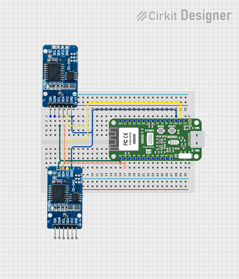
Circuit Documentation
Summary of the Circuit
The circuit in question appears to be designed for timekeeping and possibly for other time-related functions, as it includes two RTC (Real-Time Clock) DS3231 modules. These modules are known for their high accuracy and are often used in applications where precise timekeeping is critical. Additionally, there is a Glyph C3 microcontroller board, which is likely used to interface with the RTC modules and possibly perform additional processing or control functions.
Component List
RTC DS3231
- Description: A highly accurate I2C real-time clock (RTC) with an integrated temperature-compensated crystal oscillator (TCXO) and crystal.
- Pins:
32K: 32.768 kHz output pin for an external clock.SQW: Square wave/output driver pin.SCL: Serial Clock line for I2C communication.SDA: Serial Data line for I2C communication.VCC: Power supply pin.GND: Ground pin.
Glyph C3
- Description: A microcontroller board with various digital and analog I/O pins.
- Pins:
BAT / 3.7V: Battery input or 3.7V power supply.RST / EN: Reset or enable pin.USB / 5V: USB input or 5V power supply.D0 - D9: Digital I/O pins.A0 - A3: Analog input pins.SCL / IO5: I2C clock line, also used as a digital I/O.SDA / IO4: I2C data line, also used as a digital I/O.RST: Reset pin.3V3: 3.3V power output.D- / IO18,D+ / IO19: USB data lines.SCK / IO10,MO / IO6,MI / IO7: SPI pins.RX / IO20,TX / IO21: UART pins.GND: Ground pin.
Wiring Details
RTC DS3231
- SCL: Connected to the
SCL / IO5pin on the Glyph C3. - SDA: Connected to the
SDA / IO4pin on the Glyph C3. - VCC: Connected to the
3V3pin on the Glyph C3. - GND: Connected to the
GNDpin on the Glyph C3.
Glyph C3
- SCL / IO5: Connected to the
SCLpin on the RTC DS3231. - SDA / IO4: Connected to the
SDApin on the RTC DS3231. - 3V3: Connected to the
VCCpin on both RTC DS3231 modules. - GND: Connected to the
GNDpin on both RTC DS3231 modules.
Documented Code
There is no code provided for the microcontroller. In a typical application, the microcontroller would be programmed to initialize and read the time from the RTC DS3231 modules using the I2C communication protocol. The code would also handle any logic required for the application, such as setting alarms, adjusting time, or outputting the time to a display or other peripherals.
Since no code is available, it is recommended to develop firmware that initializes the I2C interface, reads the current time from the RTC modules, and provides an interface for setting and retrieving time. Additionally, error handling and power management features should be considered in the firmware design.