
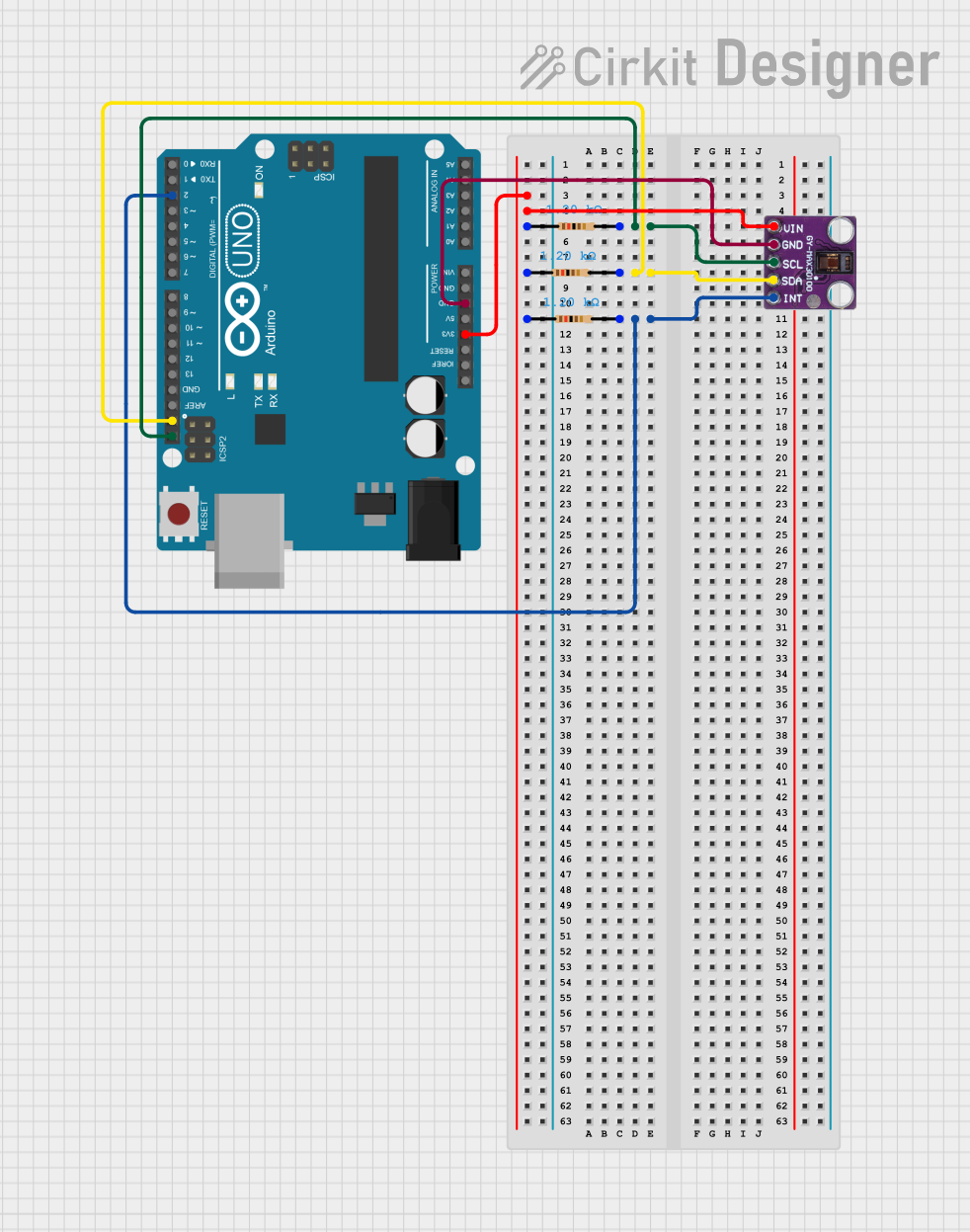
Circuit Documentation
Summary
This document provides a detailed overview of a circuit that includes an Arduino UNO microcontroller interfaced with a MAX30100 sensor module and a set of resistors. The MAX30100 is an integrated pulse oximetry and heart-rate monitor sensor solution. The circuit utilizes I2C communication protocol facilitated by pull-up resistors to connect the sensor to the microcontroller. Additionally, an interrupt line is connected to the Arduino UNO to handle events from the MAX30100 sensor.
Component List
Resistor
- Description: A resistor is a passive two-terminal electrical component that implements electrical resistance as a circuit element.
- Purpose: In this circuit, resistors are used as pull-up resistors for the I2C communication lines and the interrupt line from the MAX30100 sensor to the Arduino UNO.
- Properties: 1200 Ohms
MAX30100 Sensor Module
- Description: The MAX30100 is an integrated pulse oximetry and heart-rate monitor sensor module. It includes internal LEDs, photodetectors, optical elements, and low-noise electronics with ambient light rejection.
- Purpose: To measure pulse oximetry and heart rate in this circuit.
Arduino UNO
- Description: The Arduino UNO is a microcontroller board based on the ATmega328P. It has a variety of digital and analog I/O pins.
- Purpose: To serve as the central processing unit of the circuit, interfacing with the MAX30100 sensor module and executing the embedded code.
Wiring Details
Resistor
- Connections:
- One end connected to the 3.3V power rail from the Arduino UNO.
- The other end connected to the respective I2C communication line (SCL or SDA) or the interrupt line (INT) of the MAX30100 sensor module.
MAX30100 Sensor Module
- Connections:
Vinconnected to the 3.3V power rail through a resistor.gndconnected to the GND pin on the Arduino UNO.sclconnected to the SCL pin on the Arduino UNO through a resistor.sdaconnected to the SDA pin on the Arduino UNO through a resistor.intconnected to the D2 pin on the Arduino UNO through a resistor.
Arduino UNO
- Connections:
3.3Vproviding power to the MAX30100 sensor module and the resistors.GNDconnected to the ground pin of the MAX30100 sensor module.SCLconnected to the SCL pin of the MAX30100 sensor module through a resistor.SDAconnected to the SDA pin of the MAX30100 sensor module through a resistor.D2connected to the INT pin of the MAX30100 sensor module through a resistor.
Documented Code
Arduino UNO Code (sketch.ino)
void setup() {
  // put your setup code here, to run once:

}

void loop() {
  // put your main code here, to run repeatedly:

}
Additional Notes
- The provided code is a template and does not include specific initialization and logic required to interface with the MAX30100 sensor module.
- The user should implement the I2C communication setup in the
setup()function and the main logic to read data from the MAX30100 sensor in theloop()function. - Interrupt handling for the MAX30100 sensor should be implemented and linked to the D2 pin on the Arduino UNO.