Arduino Mega 2560-Based Access Control System with RFID and Cellular Connectivity
Circuit Documentation
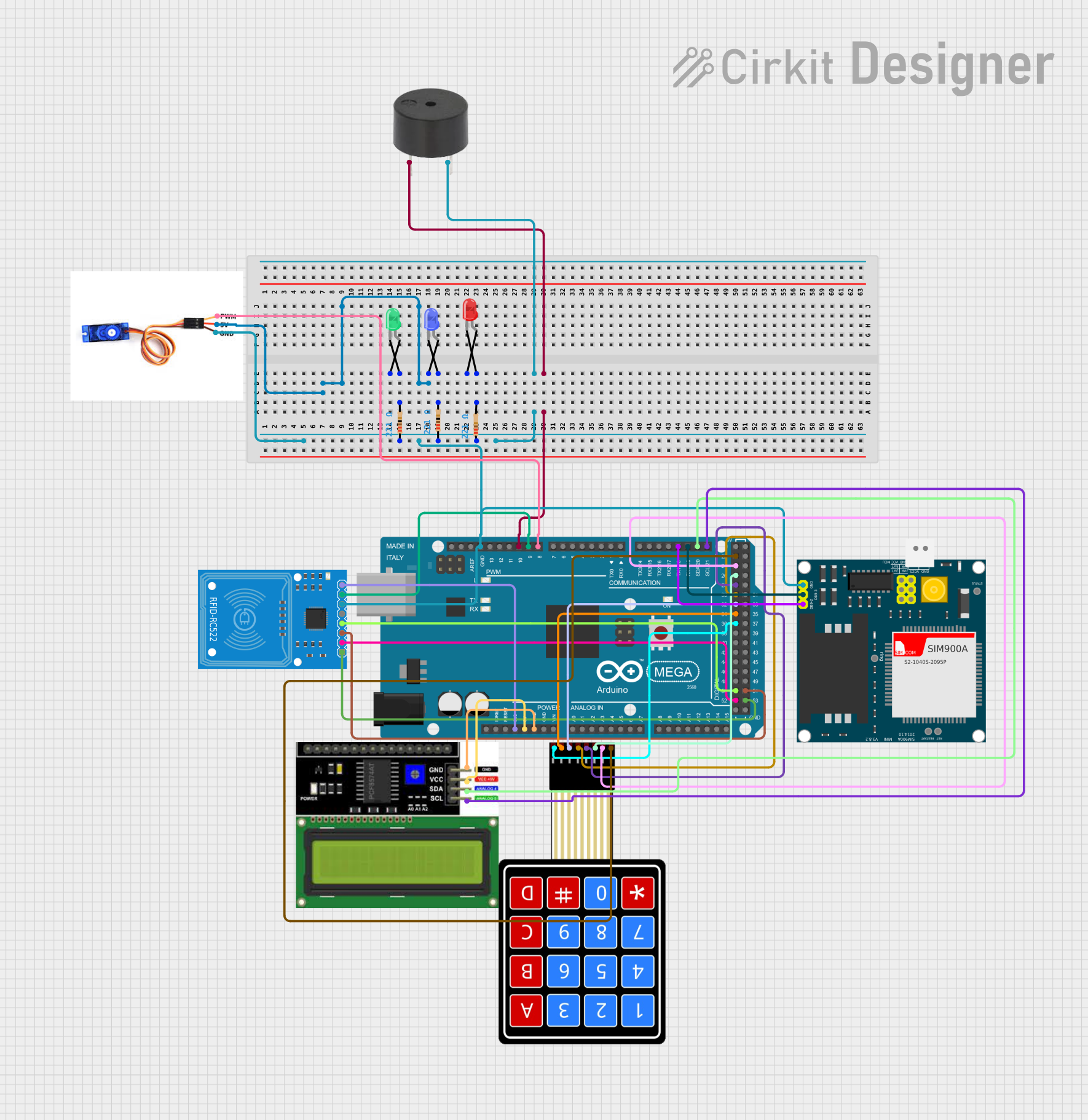
Summary
This document provides a detailed overview of a circuit designed to interface various components with an Arduino Mega 2560 microcontroller. The circuit includes input devices, output devices, and communication modules, which are interconnected through a series of electrical nets. The input devices include a 4X4 Membrane Matrix Keypad for user input. The output devices consist of a buzzer, an LCD I2C Display, and three LEDs (red, green, and blue) with corresponding resistors for current limiting. The communication modules feature an RFID-RC522 reader for RFID tag reading and a SIM900A GSM module for cellular communication. A servo motor (SG90) is also included for actuation purposes.
Component List
Buzzer
- Pins: PIN, GND
- Description: An audio signaling device.
LCD I2C Display
- Pins: GND, VCC, SDA, SCL
- Description: A display module with I2C communication interface.
RFID-RC522
- Pins: SDA, SCK, MOSI, MISO, IRQ, GND, RST, 3.3V
- Description: An RFID reader module for reading RFID tags.
SG90 Servo Motor
- Pins: PWM, 5V, GND
- Description: A small and lightweight servo motor for precise control.
4X4 Membrane Matrix Keypad
- Pins: R1, R2, R3, R4, C1, C2, C3, C4
- Description: A keypad with 16 buttons arranged in a 4x4 matrix.
Resistors (221 Ohms)
- Pins: pin1, pin2
- Description: Current-limiting resistors for LEDs.
LEDs: Two Pin (Red, Green, Blue)
- Pins: cathode, anode
- Description: Light Emitting Diodes of different colors.
Arduino Mega 2560
- Pins: Multiple digital and analog pins, power, and ground pins.
- Description: A microcontroller board based on the ATmega2560.
SIM900A
- Pins: GND, RXD, TXD, 5V, 3VR, 5VR, 3VT, 5VT, VCC, Ring, RESTART, RESET, STATUS
- Description: A GSM/GPRS module for cellular communication.
Wiring Details
Buzzer
- PIN connected to Arduino Mega 2560 (D10 PWM)
- GND connected through a resistor to Arduino Mega 2560 (GND)
LCD I2C Display
- GND connected to Arduino Mega 2560 (GND)
- VCC connected to Arduino Mega 2560 (5V)
- SDA connected to Arduino Mega 2560 (D20/SDA)
- SCL connected to Arduino Mega 2560 (D21/SCL)
RFID-RC522
- SDA connected to Arduino Mega 2560 (D53)
- SCK connected to Arduino Mega 2560 (D52)
- MOSI connected to Arduino Mega 2560 (D51)
- MISO connected to Arduino Mega 2560 (D50)
- IRQ not connected
- GND connected to Arduino Mega 2560 (GND)
- RST connected to Arduino Mega 2560 (D9 PWM)
- 3.3V connected to Arduino Mega 2560 (3V3)
SG90 Servo Motor
- PWM connected to Arduino Mega 2560 (D8 PWM)
- 5V connected to LED: Two Pin (blue) (anode)
- GND connected to Arduino Mega 2560 (GND)
4X4 Membrane Matrix Keypad
- R1 connected to Arduino Mega 2560 (D22)
- R2 connected to Arduino Mega 2560 (D24)
- R3 connected to Arduino Mega 2560 (D26)
- R4 connected to Arduino Mega 2560 (D28)
- C1 connected to Arduino Mega 2560 (D30)
- C2 connected to Arduino Mega 2560 (D32)
- C3 connected to Arduino Mega 2560 (D34)
- C4 connected to Arduino Mega 2560 (D36)
Resistors (221 Ohms)
- Each resistor has one pin connected to the cathode of an LED and the other pin connected to a common ground net.
LEDs: Two Pin (Red, Green, Blue)
- Cathode of each LED connected to a resistor (221 Ohms)
- Anode of the blue LED connected to SG90 Servo Motor (5V)
SIM900A
- RXD connected to Arduino Mega 2560 (D19/RX1)
- TXD connected to Arduino Mega 2560 (D18/TX1)
- GND connected to Arduino Mega 2560 (GND)
Documented Code
Arduino Mega 2560
void setup() {
  // put your setup code here, to run once:

}

void loop() {
  // put your main code here, to run repeatedly:

}
4X4 Membrane Matrix Keypad
void setup() {
  // put your setup code here, to run once:

}

void loop() {
  // put your main code here, to run repeatedly:

}
(Note: The code provided for the 4X4 Membrane Matrix Keypad is a placeholder and does not contain any functional code. It is expected that the user will implement the necessary code for keypad scanning and debouncing.)