
Arduino and Raspberry Pi Controlled Stepper Motor System with Pneumatic Actuation
View and Edit Project In Cirkit Designer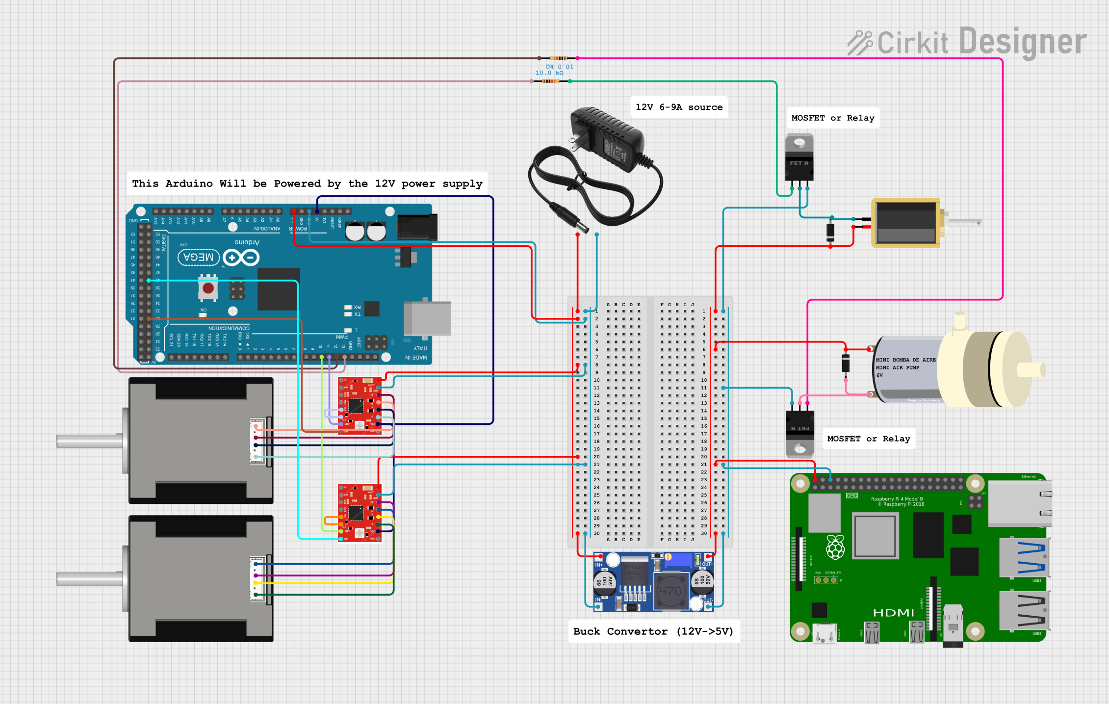
Circuit Documentation
Summary
This circuit is designed to interface an Arduino Mega 2560 with a variety of components including two A988 stepper motor drivers, two Nema 17 stepper motors, a solenoid, a mini air pump, a Raspberry Pi 4B, and several discrete components such as MOSFETs, diodes, and resistors. The circuit is powered by a 12V power supply, which is regulated down to 5V by a buck converter for certain components. The Arduino Mega 2560 serves as the central controller, managing the stepper motors, solenoid, and air pump through various outputs, including PWM and digital control signals.
Component List
- 12V Power Supply: Provides the main voltage source for the circuit.
- Buck Converter: Steps down the voltage from 12V to 5V for components requiring lower voltage.
- Arduino Mega 2560: The main microcontroller board that controls the circuit's operations.
- A988 Driver: Stepper motor driver that interfaces with the Nema 17 stepper motors.
- Nema 17 42-STH48: Stepper motor used for precision movement in applications such as robotics or CNC machines.
- Solenoid: An electromechanical device used for creating a controlled magnetic field.
- Mini Air Pump: A small pump used for moving air or other gases.
- Raspberry Pi 4B: A compact computer board that can be used for various computing tasks.
- nMOS Transistor (MOSFET): A type of transistor used for switching electronic signals.
- Diode: A component that allows current to flow in one direction only.
- Resistor: A passive two-terminal electrical component that implements electrical resistance as a circuit element.
Wiring Details
12V Power Supply
+to Arduino Mega 2560 VIN, A988 Driver VMOT (both drivers), and Buck Converter IN+.-to Arduino Mega 2560 GND, A988 Driver GND (both drivers), and Buck Converter IN-.
Buck Converter
IN+andIN-from 12V Power Supply.OUT+to Raspberry Pi 4B 5V, Diode cathodes (both diodes), and A988 Driver VDD (both drivers).OUT-to Raspberry Pi 4B GND, nMOS Transistor sources (both MOSFETs).
Arduino Mega 2560
VINfrom 12V Power Supply.GNDfrom 12V Power Supply.5Vto A988 Driver VDD (both drivers).D10 PWMto A988 Driver STEP (second driver).D11 PWMto A988 Driver STEP (first driver).D12 PWMto Resistor (second resistor).D13 PWMto Resistor (first resistor).D40to A988 Driver DIR (second driver).D30to A988 Driver DIR (first driver).
A988 Driver (First Driver)
VMOTandGNDfrom 12V Power Supply.VDDfrom Buck Converter OUT+.STEPto Arduino Mega 2560 D11 PWM.DIRto Arduino Mega 2560 D30.2Bto Nema 17 B2 Red (second motor).2Ato Nema 17 B1 Blue (second motor).1Ato Nema 17 A1 Green (second motor).1Bto Nema 17 A2 Black (second motor).RSTconnected toSLP.
A988 Driver (Second Driver)
VMOTandGNDfrom 12V Power Supply.VDDfrom Buck Converter OUT+.STEPto Arduino Mega 2560 D10 PWM.DIRto Arduino Mega 2560 D40.2Bto Nema 17 B2 Red (first motor).2Ato Nema 17 B1 Blue (first motor).1Ato Nema 17 A1 Green (first motor).1Bto Nema 17 A2 Black (first motor).RSTconnected toSLP.
Nema 17 Stepper Motors
A1 GreenandA2 Blackto A988 Driver 1A and 1B respectively (for both motors).B1 BlueandB2 Redto A988 Driver 2A and 2B respectively (for both motors).
Solenoid
pin1to Diode anode (first diode) and nMOS Transistor drain (first MOSFET).pin2to Diode cathode (first diode).
Mini Air Pump
PIN1to Diode cathode (second diode).PIN2to Diode anode (second diode) and nMOS Transistor drain (second MOSFET).
Raspberry Pi 4B
5Vfrom Buck Converter OUT+.GNDfrom Buck Converter OUT-.
nMOS Transistors (MOSFETs)
gateof both MOSFETs connected to respective Resistor pin2.drainof first MOSFET to Solenoid pin1 and Diode anode (first diode).drainof second MOSFET to Mini Air Pump PIN2 and Diode anode (second diode).sourceof both MOSFETs to Buck Converter OUT-.
Diodes
anodeof first diode to Solenoid pin1 and nMOS Transistor drain (first MOSFET).anodeof second diode to Mini Air Pump PIN2 and nMOS Transistor drain (second MOSFET).cathodeof both diodes to Buck Converter OUT+.
Resistors
pin1of first resistor to Arduino Mega 2560 D13 PWM.pin2of first resistor to nMOS Transistor gate (first MOSFET).pin1of second resistor to nMOS Transistor gate (second MOSFET).pin2of second resistor to Arduino Mega 2560 D12 PWM.
Documented Code
Arduino Mega 2560 Code (sketch.ino)
void setup() {
  // put your setup code here, to run once:

}

void loop() {
  // put your main code here, to run repeatedly:

}
Note: The provided code is a template and does not contain any functional code. It needs to be populated with the logic to control the stepper motors, solenoid, and air pump as per the requirements of the application.