
Circuit Documentation
Summary of the Circuit
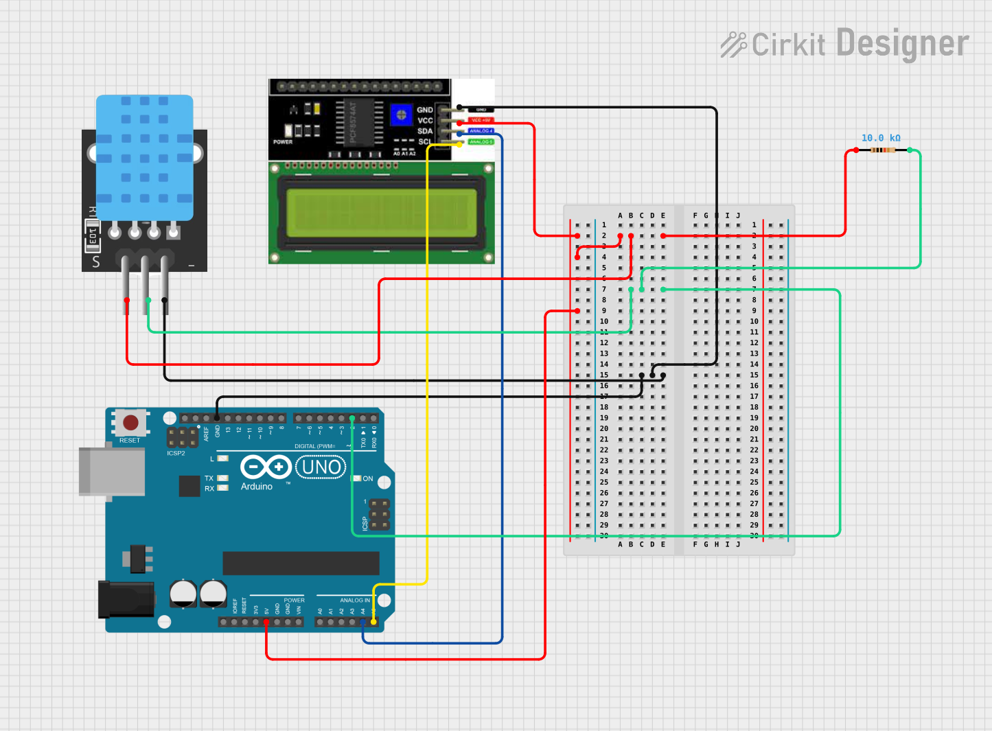
This circuit is designed to interface a temperature sensor (TEMP) with an Arduino UNO microcontroller and display the readings on an LCD I2C display. The Arduino UNO serves as the central processing unit, reading the temperature data from the TEMP sensor and sending the information to the LCD display for visualization. A resistor is included in the circuit for potential voltage division or current limiting purposes.
Component List
Temperature Sensor (TEMP)
- Pins: 5V, D3, GND
- Description: A sensor used to measure temperature.
- Purpose: To provide temperature readings to the Arduino UNO.
LCD I2C Display
- Pins: GND, VCC, SDA, SCL
- Description: A display module with I2C communication interface.
- Purpose: To display temperature readings and other information.
Arduino UNO
- Pins: UNUSED, IOREF, Reset, 3.3V, 5V, GND, Vin, A0-A5, SCL, SDA, AREF, D0-D13
- Description: A microcontroller board based on the ATmega328P.
- Purpose: To control the TEMP sensor and LCD display, process temperature data, and manage I2C communication.
Resistor
- Pins: pin1, pin2
- Description: A passive two-terminal electrical component that implements electrical resistance as a circuit element.
- Properties: 10,000 Ohms resistance
- Purpose: To limit current or divide voltage in the circuit, possibly used for the TEMP sensor.
Wiring Details
Temperature Sensor (TEMP)
- 5V: Connected to the 5V power supply from the Arduino UNO.
- D3: Connected to the digital pin D2 of the Arduino UNO.
- GND: Connected to the ground (GND) of the Arduino UNO.
LCD I2C Display
- GND: Connected to the ground (GND) of the Arduino UNO.
- VCC: Connected to the 5V power supply from the Arduino UNO.
- SDA: Connected to the analog pin A4 (SDA) of the Arduino UNO.
- SCL: Connected to the analog pin A5 (SCL) of the Arduino UNO.
Arduino UNO
- 5V: Provides power to the TEMP sensor and LCD I2C Display.
- GND: Common ground for the TEMP sensor and LCD I2C Display.
- D2: Receives the signal from the TEMP sensor.
- A4 (SDA): I2C data line connected to the LCD I2C Display.
- A5 (SCL): I2C clock line connected to the LCD I2C Display.
Resistor
- pin1: Connected to the 5V power supply from the Arduino UNO.
- pin2: Connected to the digital pin D2 of the Arduino UNO and TEMP sensor.
Documented Code
Arduino UNO Code (sketch.ino)
void setup() {
  // put your setup code here, to run once:

}

void loop() {
  // put your main code here, to run repeatedly:

}
Note: The code provided for the Arduino UNO is a template with empty setup and loop functions. The actual implementation should include initialization of the I2C communication for the LCD display, reading data from the TEMP sensor, and displaying the temperature on the LCD.
Additional Files
- documentation.txt: This file is mentioned but no content is provided. It is likely intended for additional notes or manual documentation.