Cirkit Designer
Your all-in-one circuit design IDE
Home /
Project Documentation
Arduino UNO-Based RFID and Ultrasonic Sensor Array for Automated Monitoring
Circuit Documentation
Summary
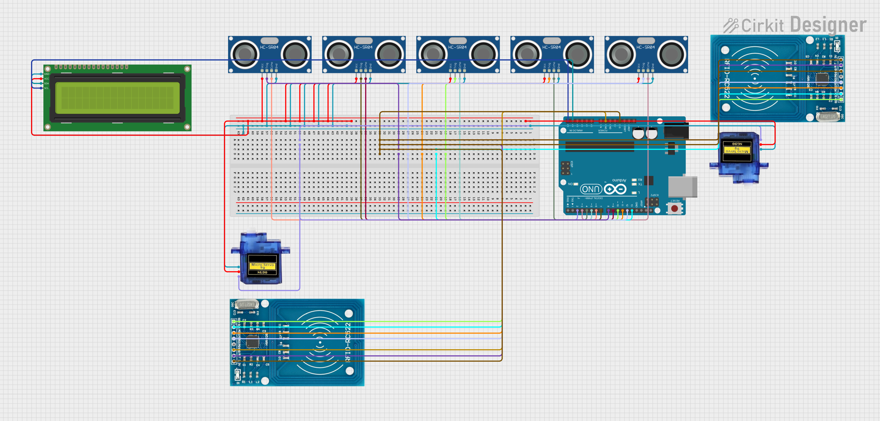
This document provides a detailed overview of a circuit that includes an Arduino UNO microcontroller, multiple HC-SR04 Ultrasonic Sensors, a 16x2 I2C LCD display, RFID-RC522 modules, and Micro servo 9G motors. The circuit is designed to interface with various sensors and modules to perform tasks that likely involve distance measurement, RFID reading, and display information on an LCD, as well as controlling servo motors.
Component List
Arduino UNO
- Microcontroller board based on the ATmega328P
- It has 14 digital input/output pins, 6 analog inputs, a 16 MHz quartz crystal, a USB connection, a power jack, an ICSP header, and a reset button.
HC-SR04 Ultrasonic Sensor
- Ultrasonic distance sensor
- Provides 2cm to 400cm non-contact measurement functionality with a ranging accuracy that can reach up to 3mm.
16x2 I2C LCD
- Alphanumeric Liquid Crystal Display
- 16 characters wide, 2 rows
- I2C communication interface
RFID-RC522
- RFID reader/writer module
- Operates at 13.56 MHz
- Communicates over SPI
Micro servo 9G
- Small-sized servo motor
- Suitable for applications where small weight and size are critical
Wiring Details
Arduino UNO
3.3Vconnected to RFID-RC522 modules'VCC (3.3V)GNDconnected to various GND pins on other componentsA4 (SDA)connected to 16x2 I2C LCD'sSDAA5 (SCL)connected to 16x2 I2C LCD'sSCLD2toD13connected to various pins on RFID-RC522 modules and HC-SR04 sensors
HC-SR04 Ultrasonic Sensors
VCCconnected to 5V power supplyGNDconnected to groundTRIGandECHOpins connected to various digital pins on the Arduino UNO
16x2 I2C LCD
GNDconnected to groundVCCconnected to 5V power supplySDAconnected to Arduino UNO'sA4 (SDA)SCLconnected to Arduino UNO'sA5 (SCL)
RFID-RC522 Modules
VCC (3.3V)connected to Arduino UNO's3.3VGNDconnected to groundSCK,MISO,MOSI,SDAconnected to corresponding SPI pins on the Arduino UNO
Micro servo 9G Motors
GNDconnected to ground+5Vconnected to 5V power supplyPWMconnected to digital pins on the Arduino UNO
Documented Code
Arduino UNO Code (sketch.ino)
void setup() {
  // put your setup code here, to run once:

}

void loop() {
  // put your main code here, to run repeatedly:

}
The provided code is a template with empty setup() and loop() functions, which are the standard structure for Arduino sketches. The setup() function is intended to contain initialization code that runs once when the program starts, and the loop() function is for code that runs continuously as long as the Arduino is powered.
Additional Notes
- There is an additional file named "documentation.txt" mentioned, but it contains no code or text.
- The actual implementation code for interfacing with the sensors, LCD, RFID modules, and servos is not provided in the input.