
ESP32-Controlled Robot with Environmental Sensing and Servo Actuation
View and Edit Project In Cirkit Designer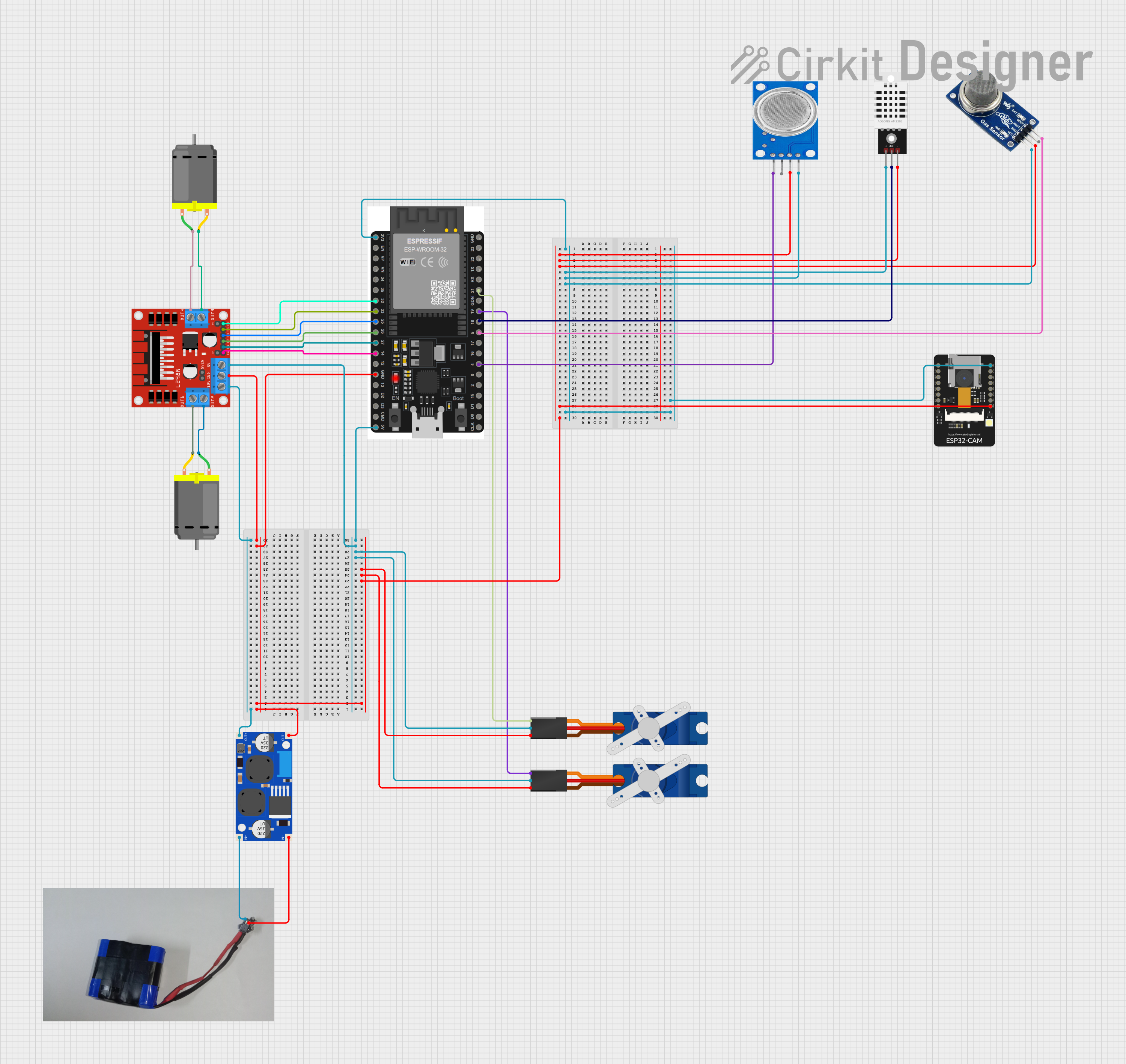
Circuit Documentation
Summary
This circuit is designed to control a Bluetooth-operated robot using an ESP32 microcontroller. The robot's movement is facilitated by two DC motors driven by an L298N motor driver. The circuit includes MQ2 and MQ135 gas sensors for environmental monitoring, a DHT22 sensor for temperature and humidity readings, and two Tower Pro SG90 servos to articulate the robot's head. The ESP32 microcontroller is programmed to interpret Bluetooth commands to control the robot's movements and to read sensor data, which is then transmitted over the serial connection.
Component List
Microcontrollers
- ESP32 38 PINS: A microcontroller with a variety of digital and analog pins, capable of Wi-Fi and Bluetooth communication.
- ESP32 - CAM: A smaller ESP32 variant with camera support.
Sensors
- MQ135: A gas sensor for detecting a wide range of gases, including NH3, NOx, alcohol, benzene, smoke, and CO2.
- MQ2: A gas sensor for detecting LPG, propane, hydrogen, and other combustible gases.
- DHT22: A sensor for measuring ambient temperature and humidity.
Actuators
- DC Motor: Two motors used for the robot's movement.
- Tower Pro SG90 servo: Two small servos for moving parts of the robot, such as the head.
Motor Driver
- L298N DC motor driver: A dual H-bridge motor driver for controlling the direction and speed of two DC motors.
Power Management
- XL6009E1 Boost Converter: A DC-DC step-up converter that increases voltage from the battery to the required level for the motors.
- Battery: The power source for the circuit.
Wiring Details
ESP32 38 PINS
- 3V3: Powers the MQ135, MQ2, DHT22, and ESP32 - CAM sensors.
- GND: Common ground for all components.
- 5V/VIN: Provides 5V to the L298N motor driver and both Tower Pro SG90 servos.
- GPIO Pins: Connected to various components for control signals.
- 21/SDA: Signal to Servo 1.
- 19: Signal to Servo 2.
- 18: Data from DHT22.
- 5: Digital output from MQ2.
- 4: Digital output from MQ135.
- 32: Enable B on L298N.
- 33: Input 4 on L298N.
- 25: Input 3 on L298N.
- 26: Input 2 on L298N.
- 27: Input 1 on L298N.
- 14: Enable A on L298N.
ESP32 - CAM
- 3V3: Powered by the ESP32 38 PINS' 3V3 output.
- GND: Connected to the common ground.
MQ135 and MQ2 Gas Sensors
- VCC: Powered by the ESP32 38 PINS' 3V3 output.
- GND: Connected to the common ground.
- D0: Digital outputs connected to the ESP32 38 PINS GPIO pins.
DHT22 Temperature and Humidity Sensor
- +: Powered by the ESP32 38 PINS' 3V3 output.
- -: Connected to the common ground.
- Out: Data connected to the ESP32 38 PINS GPIO pin.
Tower Pro SG90 Servos
- Signal: Control signals from the ESP32 38 PINS GPIO pins.
- +5V: Powered by the ESP32 38 PINS' 5V/VIN output.
- GND: Connected to the common ground.
L298N DC Motor Driver
- ENA/ENB: Enable pins controlled by the ESP32 38 PINS GPIO pins.
- IN1-IN4: Input pins for motor direction, controlled by the ESP32 38 PINS GPIO pins.
- OUT1-OUT4: Outputs connected to the DC Motors.
- 5V: Powered by the ESP32 38 PINS' 5V/VIN output.
- GND: Connected to the common ground.
- 12V: Powered by the XL6009E1 Boost Converter's OUT+.
XL6009E1 Boost Converter
- IN+/IN-: Input from the Battery.
- OUT+/OUT-: Output to the L298N motor driver.
DC Motors
- Pin 1 and Pin 2: Connected to the L298N motor driver outputs.
Battery
- Positive/Ground: Provides power to the XL6009E1 Boost Converter.
Documented Code
/*
 * This Arduino Sketch is for a Bluetooth-controlled robot using ESP32.
 * The robot can move using two DC motors controlled by an L298N driver.
 * It has MQ2 and MQ135 gas sensors, a DHT22 temperature and humidity sensor,
 * and two servo motors to move the robot's head.
 */

#include <DHT.h>
#include <Servo.h>

// Motor pins
int motor1Pin1 = 27;
int motor1Pin2 = 26;
int enable1Pin = 14;

// Servo pins
int servo1Pin = 19;
int servo2Pin = 21;

// Sensor pins
int mq2Pin = 5;
int mq135Pin = 4;
int dhtPin = 18;

// DHT22 setup
#define DHTTYPE DHT22
DHT dht(dhtPin, DHTTYPE);

// Servo setup
Servo servo1;
Servo servo2;

// PWM setup
const int freq = 30000;
const int pwmChannel = 0;
const int resolution = 8;
int dutyCycle = 170;

void setup() {
  // Motor setup
  pinMode(motor1Pin1, OUTPUT);
  pinMode(motor1Pin2, OUTPUT);
  pinMode(enable1Pin, OUTPUT);
  ledcSetup(pwmChannel, freq, resolution);
  ledcAttachPin(enable1Pin, pwmChannel);
  ledcWrite(pwmChannel, dutyCycle);

  // Servo setup
  servo1.attach(servo1Pin);
  servo2.attach(servo2Pin);

  // Sensor setup
  pinMode(mq2Pin, INPUT);
  pinMode(mq135Pin, INPUT);
  dht.begin();

  // Initialize Serial for Bluetooth communication
  Serial.begin(115200);
}

void loop() {
  // Read sensor values
  int mq2Value = digitalRead(mq2Pin);
  int mq135Value = digitalRead(mq135Pin);
  float h = dht.readHumidity();
  float t = dht.readTemperature();

  // Print sensor values to Serial
  Serial.print("MQ2: ");
  Serial.print(mq2Value);
  Serial.print(" MQ135: ");
  Serial.print(mq135Value);
  Serial.print(" Humidity: ");
  Serial.print(h);
  Serial.print("% Temperature: ");
  Serial.print(t);
  Serial.println("*C");

  // Check for Bluetooth commands
  if (Serial.available() > 0) {
    char command = Serial.read();
    handleCommand(command);
  }

  delay(100);
}

void handleCommand(char command) {
  switch (command) {
    case 'F': // Move forward
      digitalWrite(motor1Pin1, HIGH);
      digitalWrite(motor1Pin2, LOW);
      break;
    case 'B': // Move backward
      digitalWrite(motor1Pin1, LOW);
      digitalWrite(motor1Pin2, HIGH);
      break;
    case 'L': // Turn left
      servo1.write(45);
      break;
    case 'R': // Turn right
      servo1.write(135);
      break;
    case 'S': // Stop
      digitalWrite(motor1Pin1, LOW);
      digitalWrite(motor1Pin2, LOW);
      break;
    case 'U': // Move head up
      servo2.write(45);
      break;
    case 'D': // Move head down
      servo2.write(135);
      break;
    default:
      break;
  }
}
This code is responsible for initializing and controlling the various components of the robot. It sets up the motor and servo pins, initializes the sensors, and enters a loop where it reads sensor values and listens for Bluetooth commands to control the robot's movements and head position.