
Arduino UNO Based Environmental Monitoring and Security System
View and Edit Project In Cirkit Designer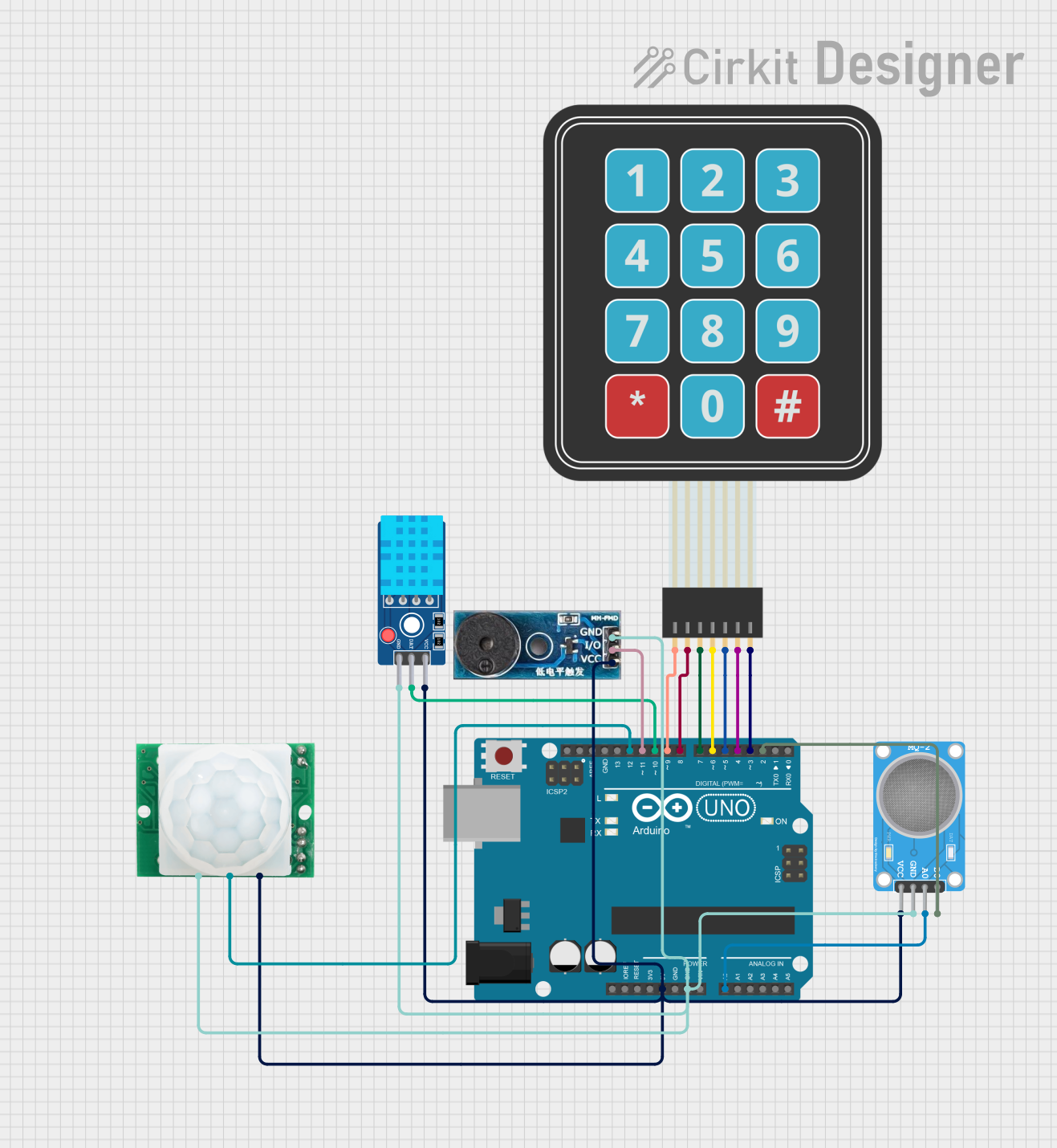
Circuit Documentation
Summary of the Circuit
This circuit is designed around the Arduino UNO microcontroller, which serves as the central processing unit for various sensors and input/output devices. The circuit includes a DHT11 temperature and humidity sensor, an MQ-2 gas sensor, an HC-SR501 motion sensor, a membrane matrix keypad for user input, and a buzzer module for audio feedback. The sensors and the keypad provide input to the Arduino, which processes the data and can trigger the buzzer based on certain conditions. The circuit is powered by the Arduino's 5V output, and all components share a common ground.
Component List
Arduino UNO
- Microcontroller board based on the ATmega328P
- Provides digital and analog I/O pins
- Powers the circuit and processes sensor data
DHT11 Sensor V2
- Digital temperature and humidity sensor
- Provides ambient temperature and humidity readings
MQ-2 SENSOR
- Combustible gas and smoke sensor
- Provides analog and digital outputs indicating gas presence
Membrane Matrix Keypad
- Input device with rows and columns of buttons
- Allows user interaction with the circuit
Buzzer Module
- Audio signaling device
- Can produce a tone when activated
HC-SR501 Motion sensor
- Passive infrared sensor for detecting motion
- Provides a digital output when motion is detected
Wiring Details
Arduino UNO
- 5V pin connected to the VCC pins of DHT11 Sensor V2, MQ-2 SENSOR, HC-SR501 Motion sensor, and Buzzer Module
- GND pin connected to the GND pins of DHT11 Sensor V2, MQ-2 SENSOR, HC-SR501 Motion sensor, and Buzzer Module
- A0 pin connected to the A0 pin of MQ-2 SENSOR
- D12 pin connected to the OUT pin of HC-SR501 Motion sensor
- D11 pin connected to the I/O pin of Buzzer Module
- D10 pin connected to the DAT pin of DHT11 Sensor V2
- D9 to D3 pins connected to the Row 1 to Row 4 and Column 1 to Column 3 pins of Membrane Matrix Keypad respectively
- D2 pin connected to the D0 pin of MQ-2 SENSOR
DHT11 Sensor V2
- VCC pin connected to 5V of Arduino UNO
- GND pin connected to GND of Arduino UNO
- DAT pin connected to D10 of Arduino UNO
MQ-2 SENSOR
- VCC pin connected to 5V of Arduino UNO
- GND pin connected to GND of Arduino UNO
- A0 pin connected to A0 of Arduino UNO
- D0 pin connected to D2 of Arduino UNO
Membrane Matrix Keypad
- Row 1 to Row 4 pins connected to D9 to D6 of Arduino UNO respectively
- Column 1 to Column 3 pins connected to D5 to D3 of Arduino UNO respectively
Buzzer Module
- Vcc pin connected to 5V of Arduino UNO
- GND pin connected to GND of Arduino UNO
- I/O pin connected to D11 of Arduino UNO
HC-SR501 Motion sensor
- VCC pin connected to 5V of Arduino UNO
- GND pin connected to GND of Arduino UNO
- OUT pin connected to D12 of Arduino UNO
Documented Code
Arduino UNO Code (sketch.ino)
void setup() {
  // put your setup code here, to run once:

}

void loop() {
  // put your main code here, to run repeatedly:

}
Note: The provided code is a template and does not include specific functionality. It should be populated with setup configurations and operational logic based on the desired behavior of the circuit.