Battery-Powered ESP32 Smart Display with Fingerprint Sensor
Circuit Documentation
Summary
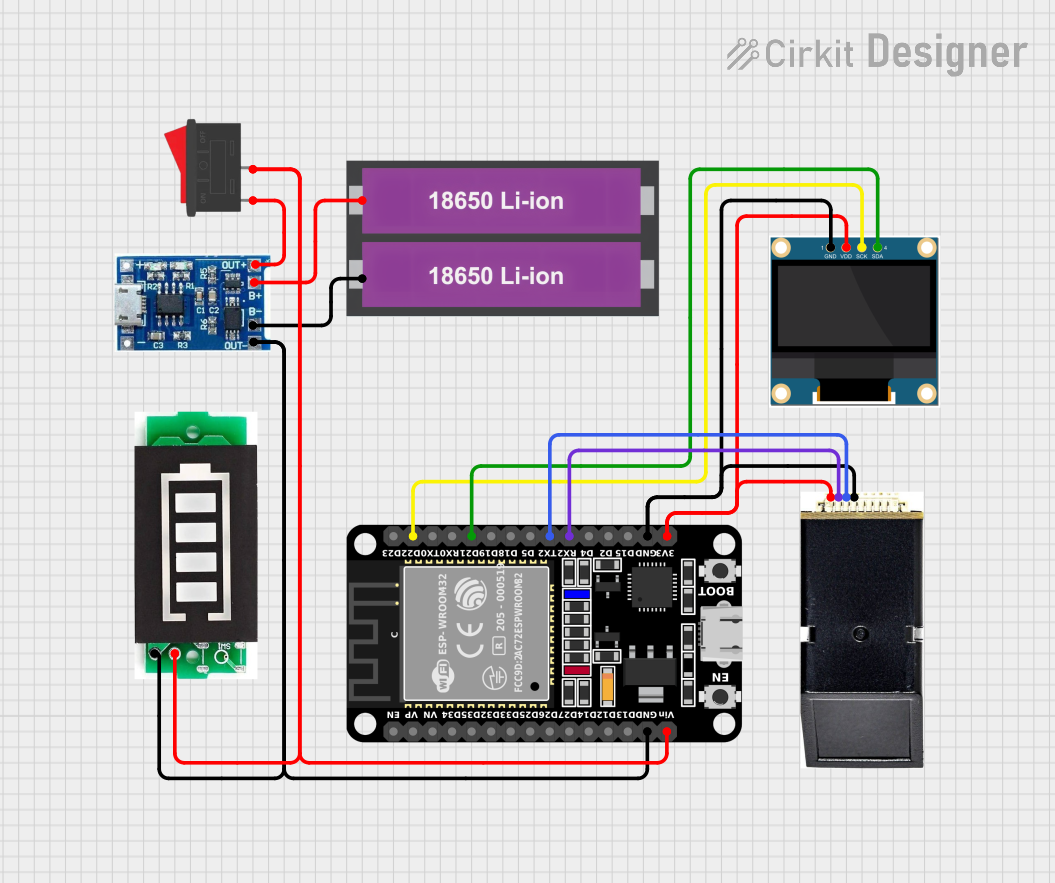
This document provides a detailed overview of a circuit design that includes an ESP32 microcontroller, a 0.96" OLED display, a LiPo battery charger module, two 18650 Li-ion batteries, a rocker switch, a battery indicator, and an AS608 fingerprint sensor. The circuit is designed to be powered by the Li-ion batteries and includes a charging module for recharging the batteries. The ESP32 microcontroller interfaces with the OLED display and the fingerprint sensor.
Component List
ESP32 (30 pin)
- Description: A powerful microcontroller with built-in Wi-Fi and Bluetooth capabilities.
- Pins: EN, VP, VN, D34, D35, D32, D33, D25, D26, D27, D14, D12, D13, GND, Vin, D23, D22, TX0, RX0, D21, D19, D18, D5, TX2, RX2, D4, D2, D15, 3V3
0.96" OLED
- Description: A small OLED display used for visual output.
- Pins: GND, VDD, SCK, SDA
LiPo Battery Charger Module
- Description: A module used to charge LiPo batteries.
- Pins: B-, B+, OUT-, OUT+
18650 Li-ion Battery x 2
- Description: Rechargeable Li-ion batteries used to power the circuit.
- Pins: +, -
Rocker Switch
- Description: A switch used to control the power supply to the circuit.
- Pins: 1, 2
Battery Indicator
- Description: A module used to indicate the battery level.
- Pins: +, -
AS608
- Description: A fingerprint sensor used for biometric authentication.
- Pins: VCC, TX, GND, RX
Wiring Details
ESP32 (30 pin)
GND is connected to:
- LiPo Battery Charger Module (OUT-)
- Battery Indicator (-)
- 0.96" OLED (GND)
- AS608 (GND)
Vin is connected to:
- Battery Indicator (+)
- Rocker Switch (2)
D22 is connected to:
- 0.96" OLED (SCK)
D21 is connected to:
- 0.96" OLED (SDA)
TX2 is connected to:
- AS608 (RX)
RX2 is connected to:
- AS608 (TX)
3V3 is connected to:
- 0.96" OLED (VDD)
- AS608 (VCC)
0.96" OLED
GND is connected to:
- ESP32 (GND)
- AS608 (GND)
VDD is connected to:
- ESP32 (3V3)
- AS608 (VCC)
SCK is connected to:
- ESP32 (D22)
SDA is connected to:
- ESP32 (D21)
LiPo Battery Charger Module
OUT- is connected to:
- ESP32 (GND)
- Battery Indicator (-)
OUT+ is connected to:
- Rocker Switch (1)
B- is connected to:
- 18650 Li-ion Battery (-)
B+ is connected to:
- 18650 Li-ion Battery (+)
18650 Li-ion Battery x 2
- is connected to:
- LiPo Battery Charger Module (B-)
+ is connected to:
- LiPo Battery Charger Module (B+)
Rocker Switch
1 is connected to:
- LiPo Battery Charger Module (OUT+)
2 is connected to:
- ESP32 (Vin)
- Battery Indicator (+)
Battery Indicator
- is connected to:
- LiPo Battery Charger Module (OUT-)
- ESP32 (GND)
+ is connected to:
- ESP32 (Vin)
- Rocker Switch (2)
AS608
GND is connected to:
- 0.96" OLED (GND)
- ESP32 (GND)
VCC is connected to:
- 0.96" OLED (VDD)
- ESP32 (3V3)
TX is connected to:
- ESP32 (RX2)
RX is connected to:
- ESP32 (TX2)
Code
No code is provided for this circuit.
This document provides a comprehensive overview of the circuit design, including a detailed list of components and their wiring connections. This should serve as a useful reference for building and troubleshooting the circuit.