
Peltier-Controlled Thermal Management System with SPST Switch
View and Edit Project In Cirkit Designer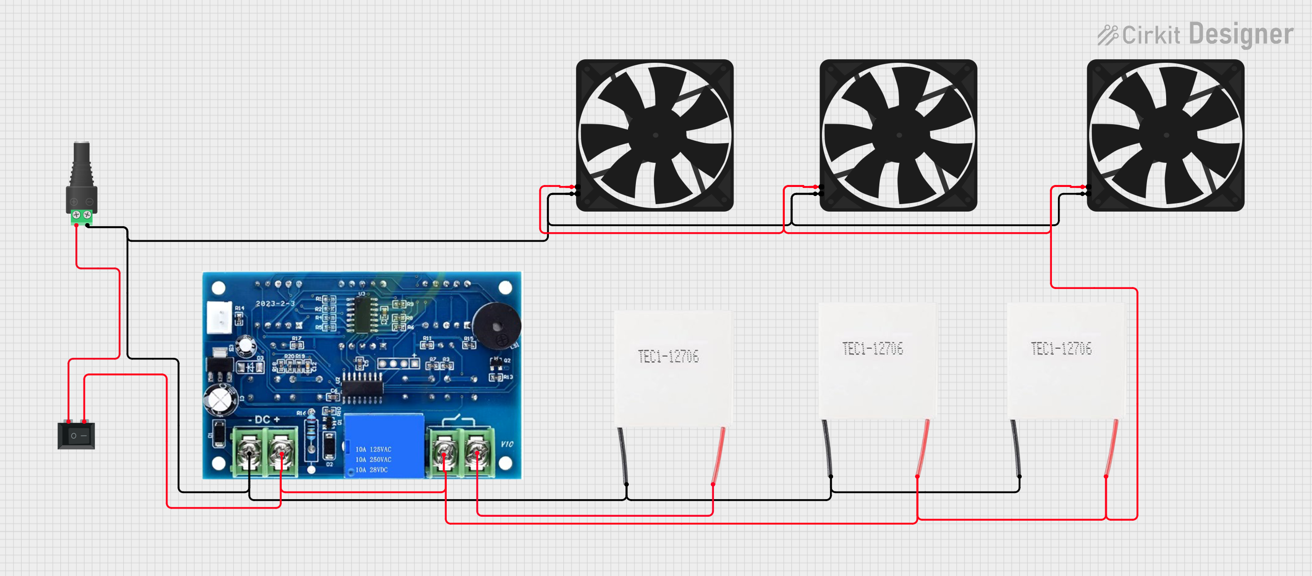
Circuit Documentation
Summary of the Circuit
The circuit in question appears to be designed to control and power multiple Peltier modules and fans, likely for a cooling or thermoelectric application. The circuit includes a digital controller, multiple fans, Peltier modules, a barrel jack for power input, and a rocker switch to control the power flow. The digital controller is responsible for managing the power distribution to the Peltier modules and fans. The rocker switch allows the user to turn the system on or off. The barrel jack provides a means to connect an external power source to the circuit.
Component List
Digital Controller
- Description: A digital control unit used to manage power distribution within the circuit.
- Pins:
+,-
Fans
- Description: Fans used to dissipate heat, likely from the Peltier modules.
- Pins:
GND,5V
Peltier Modules
- Description: Thermoelectric modules used for heating or cooling applications.
- Pins:
Negative,Positive
2.1mm Barrel Jack with Terminal Block
- Description: A connector used for attaching an external power supply to the circuit.
- Pins:
POS,NEG
Rocker Switch (SPST)
- Description: A single-pole single-throw switch used to control the power flow in the circuit.
- Pins:
1,2
Wiring Details
Digital Controller
- Positive Pin: Connected to the positive pins of all Peltier modules.
- Negative Pin: Connected to the negative pins of all Peltier modules and the ground pins of all fans.
Fans
- 5V Pin: Connected to the positive pin of the digital controller and the positive pin of the Peltier modules.
- GND Pin: Connected to the negative pin of the digital controller and the negative pins of the Peltier modules.
Peltier Modules
- Positive Pin: Connected to the positive pin of the digital controller, the second pin of the rocker switch, and the 5V pins of the fans.
- Negative Pin: Connected to the negative pin of the digital controller, the ground pins of the fans, and the negative terminal of the barrel jack.
2.1mm Barrel Jack with Terminal Block
- POS Pin: Connected to the first pin of the rocker switch.
- NEG Pin: Connected to the negative pins of the Peltier modules and the ground pins of the fans.
Rocker Switch (SPST)
- Pin 1: Connected to the positive terminal of the barrel jack.
- Pin 2: Connected to the positive pins of the Peltier modules and the 5V pins of the fans.
Documented Code
There is no embedded code provided for any microcontrollers in this circuit. If there were microcontrollers and associated code, this section would include the code with comments explaining its functionality and how it interacts with the hardware components of the circuit.