
Circuit Documentation
Summary
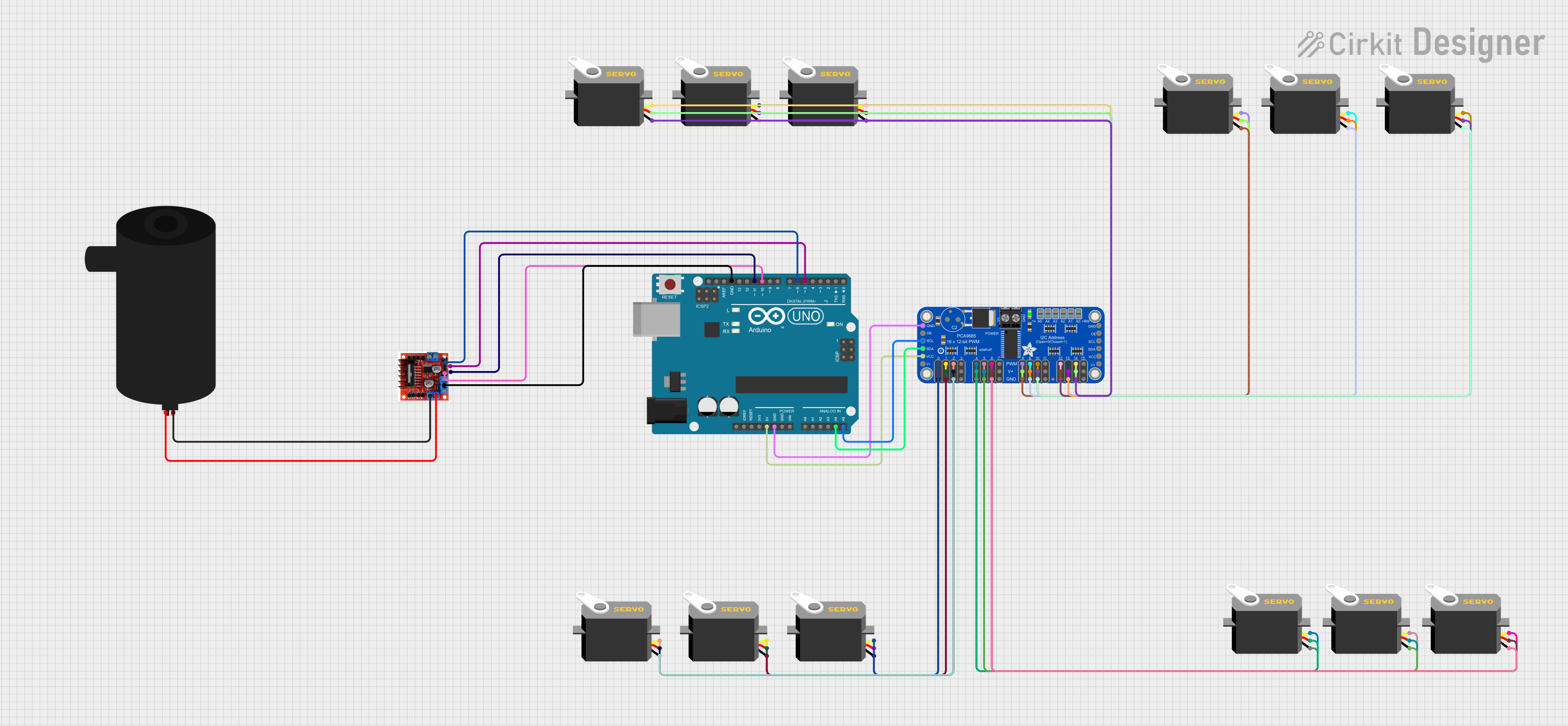
This circuit is designed to control multiple servo motors using an Arduino UNO as the main microcontroller and an Adafruit PCA9685 PWM Servo Breakout to extend the number of PWM outputs. Additionally, the circuit includes an L298N Motor Driver to control a water pump. The Arduino UNO communicates with the PCA9685 via I2C protocol, using its A4 and A5 pins for SDA and SCL lines, respectively. The servos are powered by the 5V provided by the PCA9685, and the water pump is driven by the L298N Motor Driver, which is controlled by the Arduino UNO using digital pins D5, D6, D10, and D11.
Component List
- Arduino UNO: A microcontroller board based on the ATmega328P, featuring digital and analog I/O pins.
- Adafruit PCA9685 PWM Servo Breakout: A 16-channel, 12-bit PWM Fm+ I2C-bus LED controller, commonly used for controlling servos.
- Servo Motors: Actuators that can be precisely controlled for position using PWM signals.
- L298N Motor Driver Controller Board Module: A high-power motor driver module capable of driving inductive loads such as relays, solenoids, and DC and stepping motors.
- Water Pump: An electric pump for moving water, controlled by the L298N Motor Driver.
Wiring Details
Arduino UNO
- 5V: Provides power to the Adafruit PCA9685 PWM Servo Breakout.
- GND: Connected to the ground (GND) of the Adafruit PCA9685 and the L298N Motor Driver.
- A4 (SDA): I2C data line connected to the SDA pin of the Adafruit PCA9685.
- A5 (SCL): I2C clock line connected to the SCL pin of the Adafruit PCA9685.
- D5: Connected to Input 3 on the L298N Motor Driver.
- D6: Connected to Input 4 on the L298N Motor Driver.
- D10: Connected to Input 1 on the L298N Motor Driver.
- D11: Connected to Input 2 on the L298N Motor Driver.
Adafruit PCA9685 PWM Servo Breakout
- VCC (5V): Receives power from the Arduino UNO 5V pin.
- GND: Connected to the ground (GND) of the Arduino UNO.
- SDA: I2C data line connected to the A4 pin of the Arduino UNO.
- SCL: I2C clock line connected to the A5 pin of the Arduino UNO.
- PWM Channels (0-15): Each channel is connected to the pulse pin of a corresponding servo motor.
- 5.0V: Provides power to the servo motors.
- GND: Connected to the ground (GND) of the servo motors.
Servo Motors
- VCC (5V): Receives power from the 5.0V pin of the Adafruit PCA9685.
- GND: Connected to the ground (GND) of the Adafruit PCA9685.
- Pulse: Receives PWM signal from a corresponding PWM channel on the Adafruit PCA9685.
L298N Motor Driver Controller Board Module
- Ground: Connected to the ground (GND) of the Arduino UNO.
- Input 1-4: Controlled by the Arduino UNO digital pins D5, D6, D10, and D11.
- Output A: Connected to the positive terminal of the water pump.
- Output B: Not used in this circuit.
Water Pump
- Positive: Connected to Output A of the L298N Motor Driver.
- Negative: Connected to the ground (GND) of the L298N Motor Driver.
Documented Code
Arduino UNO Code (sketch.ino)
void setup() {
  // put your setup code here, to run once:

}

void loop() {
  // put your main code here, to run repeatedly:

}
This code is a template and does not contain any specific functionality. It should be populated with the initialization code in the setup() function and the main control code in the loop() function to control the servos and the water pump via the L298N Motor Driver.
Additional Notes
- The provided code is a placeholder and needs to be completed with the actual logic for controlling the servos and the water pump.
- The Adafruit PCA9685 requires initialization and setup to generate the correct PWM signals for the servo motors.
- The L298N Motor Driver inputs need to be driven with the correct logic levels to control the water pump's operation.