Solar-Powered Dual Source Automatic Transfer Switch System
Circuit Documentation
Summary of the Circuit
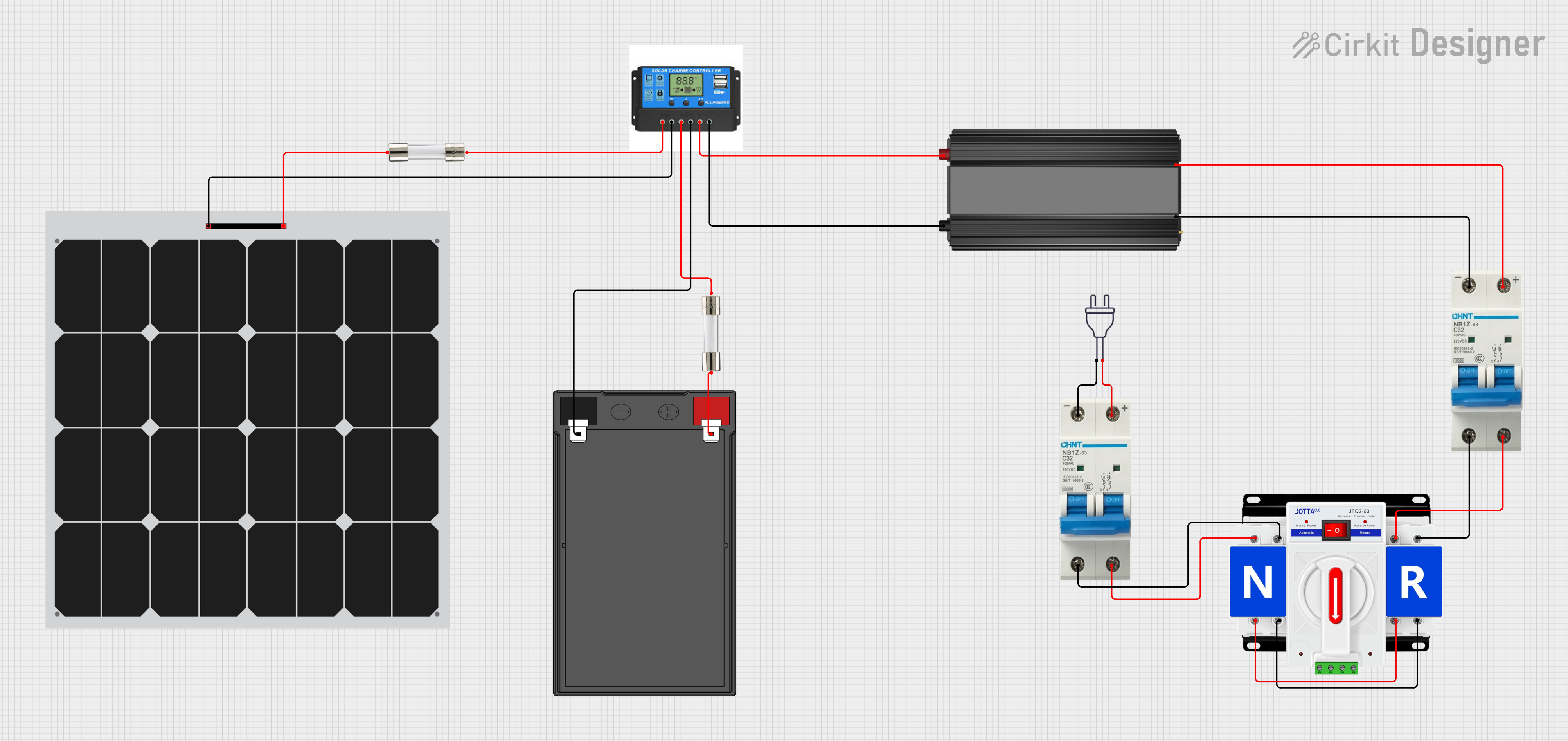
This circuit appears to be a power management system that integrates a solar panel with a 12V battery, a charge controller, and a power inverter to provide a 220V AC output. The system includes safety features such as fuses and circuit breakers to protect against overcurrent conditions. A dual power automatic transfer switch is included, suggesting the system can switch between different power sources. However, without a microcontroller or control logic, the automatic functionalities of the transfer switch are not defined in this documentation.
Component List
12v 7ah Battery
- Description: A rechargeable battery providing a nominal 12V output.
- Pins: 12v +, 12v -
Fuse
- Description: A protective device that interrupts the circuit when excessive current flows.
- Pins: Terminal 1, Terminal 2
Circuit Breaker
- Description: An automatically operated electrical switch designed to protect an electrical circuit from damage caused by overload or short circuit.
- Pins: -, +
Dual Power Automatic Transfer Switch
- Description: A switch that automatically transfers a load between two power sources.
- Pins: +, -
Solar Panel
- Description: A panel designed to absorb the sun's rays as a source of energy for generating electricity.
- Pins: +, -
Charge Controller
- Description: A device that regulates the voltage and current coming from the solar panels going to the battery.
- Pins: Solar Positive, Solar Negative, Battery Positive, Battery Negative, Load Positive, Load Negative
Power Inverter
- Description: A device that converts DC power from the battery to AC power.
- Pins: -, +
Power 220v
- Description: Represents the output terminals for a 220V AC power source.
- Pins: Hot wire, Neutral wire
Wiring Details
12v 7ah Battery
- 12v + connected to Fuse (Terminal 1)
- 12v - connected to Charge Controller (Battery Negative)
Fuse (Battery Side)
- Terminal 1 connected to 12v 7ah Battery (12v +)
- Terminal 2 connected to Charge Controller (Battery Positive)
Fuse (Solar Side)
- Terminal 1 connected to Solar Panel (+)
- Terminal 2 connected to Charge Controller (Solar Positive)
Circuit Breaker (Battery Side)
- connected to Power Inverter (+)
- connected to Power Inverter (-)
Circuit Breaker (Mains Side)
- connected to Power 220v (Neutral wire)
- connected to Power 220v (Hot wire)
Dual Power Automatic Transfer Switch
- connected to Circuit Breaker (+) on both sides
- connected to Circuit Breaker (-) on both sides
Solar Panel
- connected to Fuse (Terminal 1)
- connected to Charge Controller (Solar Negative)
Charge Controller
- Solar Positive connected to Fuse (Terminal 2)
- Solar Negative connected to Solar Panel (-)
- Battery Positive connected to Fuse (Terminal 2)
- Battery Negative connected to 12v 7ah Battery (12v -)
- Load Positive connected to Power Inverter (+)
- Load Negative connected to Power Inverter (-)
Power Inverter
- connected to Charge Controller (Load Positive) and Circuit Breaker (+)
- connected to Charge Controller (Load Negative) and Circuit Breaker (-)
Power 220v
- Hot wire connected to Circuit Breaker (-)
- Neutral wire connected to Circuit Breaker (+)
Documented Code
No code has been provided for any microcontrollers within the circuit. Therefore, there is no embedded code to document at this time. If the system is intended to have automatic functionalities or monitoring capabilities, it would require a microcontroller or other control logic with associated code, which should be included in future documentation updates.