Cirkit Designer
Your all-in-one circuit design IDE
Home /
Project Documentation
ESP8266 NodeMCU Controlled 4-Channel Relay for Smart AC Lighting
Circuit Documentation
Summary
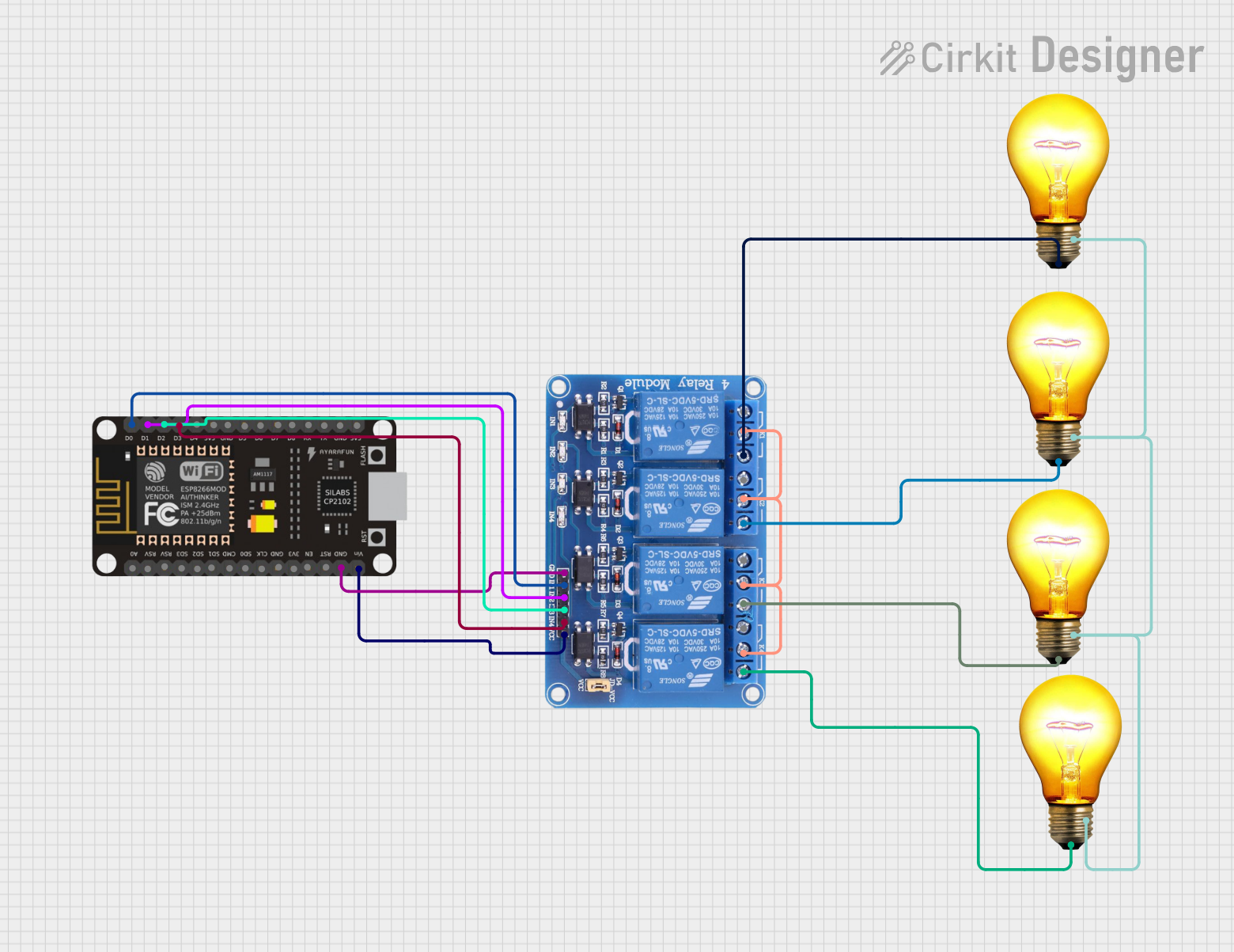
The circuit in question is designed to control four AC bulbs using an ESP8266 NodeMCU microcontroller and a 4-channel 5V relay module. The ESP8266 NodeMCU is interfaced with the relay module to switch the AC bulbs on and off. The relay module acts as an electrically operated switch that allows the low-power microcontroller to control the high-power circuit of the AC bulbs.
Component List
ESP8266 NodeMCU
- Description: A Wi-Fi enabled microcontroller module with GPIO pins.
- Pins: D0, D1, D2, D3, D4, 3V3, GND, D5, D6, D7, D8, RX, TX, A0, RSV, SD3, SD2, SD1, CMD, SD0, CLK, EN, RST, VIN
Relay 4 Channel 5V
- Description: A 4-channel relay module capable of controlling up to four separate high-power devices.
- Pins: GND, IN1, IN2, IN3, IN4, VCC, COM1, COM2, COM3, COM4, NO1, NO2, NO3, NO4, NC1, NC2, NC3, NC4
AC Bulb (x4)
- Description: A standard AC bulb for illumination.
- Pins: P (Phase), N (Neutral)
Wiring Details
ESP8266 NodeMCU
- D0 connected to Relay IN1
- D1 connected to Relay IN2
- D2 connected to Relay IN3
- D3 connected to Relay IN4
- GND connected to Relay GND
- VIN connected to Relay VCC
Relay 4 Channel 5V
- GND connected to ESP8266 NodeMCU GND
- IN1 connected to ESP8266 NodeMCU D0
- IN2 connected to ESP8266 NodeMCU D1
- IN3 connected to ESP8266 NodeMCU D2
- IN4 connected to ESP8266 NodeMCU D3
- VCC connected to ESP8266 NodeMCU VIN
- COM1-4 interconnected
- NO1 connected to AC Bulb 1 P
- NO2 connected to AC Bulb 2 P
- NO3 connected to AC Bulb 3 P
- NO4 connected to AC Bulb 4 P
AC Bulb
- P (Phase) of each bulb connected to respective NO terminals on Relay
- N (Neutral) of all bulbs interconnected
Documented Code
Microcontroller Code (sketch.ino)
void setup() {
  // put your setup code here, to run once:

}

void loop() {
  // put your main code here, to run repeatedly:

}
Additional Notes (documentation.txt)
No additional code documentation provided.
This documentation provides an overview of the circuit components, their wiring, and the initial code structure for the ESP8266 NodeMCU. Further details, such as the specific functionality within the setup() and loop() functions, would be necessary to fully understand the operation of the circuit.