
Battery-Powered 18650 Li-ion Charger with USB Output and Adjustable Voltage Regulator
View and Edit Project In Cirkit Designer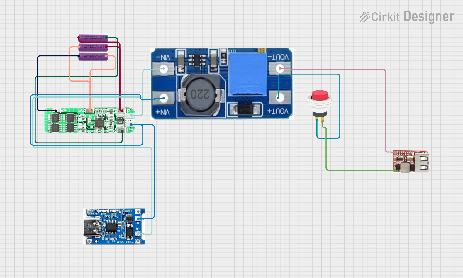
Circuit Documentation
Summary
This document provides a detailed overview of a circuit designed to manage and regulate power from multiple 3.7V batteries through a protection board, a step-up boost converter, and a USB regulator. The circuit includes a push switch for user control and a TP4056 module for battery charging protection.
Component List
3.7V Battery
- Description: Standard lithium-ion battery.
- Pins: +, -
3S 10A Li-ion 18650 Charger Protection Board Module
- Description: Protection board for 3S Li-ion battery packs.
- Pins: B+, B2, B1, P-, P+, B-
Step Up Boost Power Converter, Adjustable Voltage Regulator
- Description: Boost converter to step up voltage.
- Pins: VOUT+, VOUT-, VIN+, VIN-
USB Regulator
- Description: Regulates voltage to USB standard.
- Pins: VIN+, VIN-, 5V_USB_VO
TP4056 Battery Charging Protection Module (Type C)
- Description: Battery charging and protection module.
- Pins: OUT +, B+, B-, OUT -, +, -
2Pin Push Switch
- Description: Simple push switch for user control.
- Pins: Input +, Output +
Wiring Details
3.7V Battery
Battery 1:
- + connected to B1 of the 3S 10A Li-ion 18650 Charger Protection Board Module.
- - connected to B- of the 3S 10A Li-ion 18650 Charger Protection Board Module.
Battery 2:
- + connected to B+ of the 3S 10A Li-ion 18650 Charger Protection Board Module.
- - connected to B2 of the 3S 10A Li-ion 18650 Charger Protection Board Module.
Battery 3:
- + connected to B2 of the 3S 10A Li-ion 18650 Charger Protection Board Module.
- - connected to B1 of the 3S 10A Li-ion 18650 Charger Protection Board Module.
3S 10A Li-ion 18650 Charger Protection Board Module
- B1 connected to + of Battery 1 and - of Battery 3.
- B- connected to - of Battery 1.
- B+ connected to + of Battery 2.
- B2 connected to - of Battery 2 and + of Battery 3.
- P- connected to VIN- of the Step Up Boost Power Converter and B- of the TP4056 Battery Charging Protection Module.
- P+ connected to VIN+ of the Step Up Boost Power Converter and B+ of the TP4056 Battery Charging Protection Module.
Step Up Boost Power Converter, Adjustable Voltage Regulator
- VIN- connected to P- of the 3S 10A Li-ion 18650 Charger Protection Board Module and B- of the TP4056 Battery Charging Protection Module.
- VIN+ connected to P+ of the 3S 10A Li-ion 18650 Charger Protection Board Module and B+ of the TP4056 Battery Charging Protection Module.
- VOUT+ connected to Input + of the 2Pin Push Switch.
- VOUT- connected to VIN- of the USB Regulator.
USB Regulator
- VIN+ connected to Output + of the 2Pin Push Switch.
- VIN- connected to VOUT- of the Step Up Boost Power Converter.
TP4056 Battery Charging Protection Module (Type C)
- B- connected to P- of the 3S 10A Li-ion 18650 Charger Protection Board Module and VIN- of the Step Up Boost Power Converter.
- B+ connected to P+ of the 3S 10A Li-ion 18650 Charger Protection Board Module and VIN+ of the Step Up Boost Power Converter.
2Pin Push Switch
- Input + connected to VOUT+ of the Step Up Boost Power Converter.
- Output + connected to VIN+ of the USB Regulator.
Code
No microcontroller code is included in this circuit.