
Circuit Documentation
Summary of the Circuit
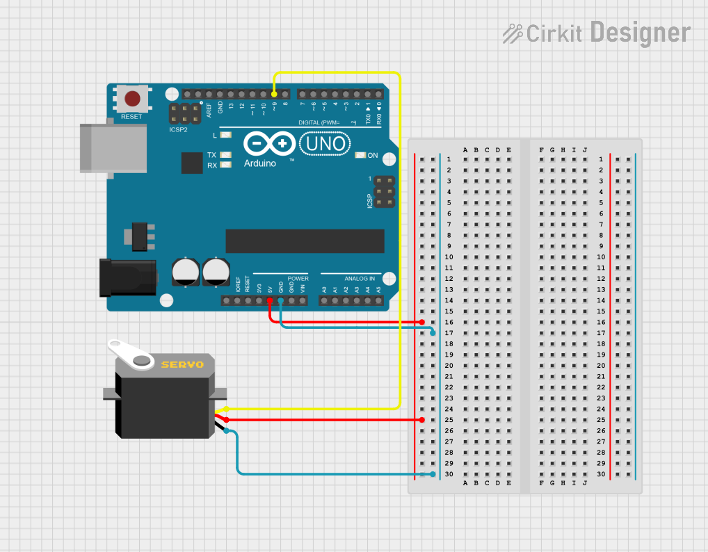
This circuit consists of an Arduino UNO microcontroller board that is interfaced with a servo motor. The Arduino UNO provides control signals to the servo motor, as well as power and ground connections. The servo motor is expected to receive pulse width modulation (PWM) signals from one of the digital pins of the Arduino to control its position.
Component List
Arduino UNO
- Description: A microcontroller board based on the ATmega328P.
- Pins: UNUSED, IOREF, Reset, 3.3V, 5V, GND, Vin, A0-A5, SCL, SDA, AREF, D0-D13.
- Purpose: Acts as the main controller for the circuit, providing logic and control signals to the servo motor.
Servo
- Description: An actuator that can be precisely controlled for angular or linear position, speed, and acceleration.
- Pins: gnd, vcc, pulse.
- Purpose: Executes physical movements based on the PWM signals received from the Arduino UNO.
Wiring Details
Arduino UNO
- 5V: Provides power to the servo motor.
- GND: Common ground with the servo motor.
- D9: Outputs PWM signal to control the servo motor.
Servo
- vcc: Connected to the 5V output from the Arduino UNO.
- gnd: Connected to the ground (GND) on the Arduino UNO.
- pulse: Receives PWM control signal from pin D9 of the Arduino UNO.
Documented Code
Arduino UNO Code (sketch.ino)
void setup() {
  // put your setup code here, to run once:

}

void loop() {
  // put your main code here, to run repeatedly:

}
Additional Notes
- The provided code is a template and does not contain any specific logic for controlling the servo motor. The user is expected to fill in the setup and loop functions with the necessary code to generate PWM signals and control the servo motor's position.
- The
setup()function is used to initialize variables, pin modes, start using libraries, etc. The code inside it runs once after each power-up or reset of the Arduino board. - The
loop()function is used for the main program logic. It runs continuously after thesetup()function completes. - The servo motor control pin is connected to pin D9 of the Arduino UNO, which is capable of PWM output required for servo control.
This documentation provides an overview of the circuit's components, their purposes, and the wiring connections between them. The code section includes a basic template for the Arduino sketch, which needs to be completed with the actual control logic for the servo motor.