
Circuit Documentation
Summary
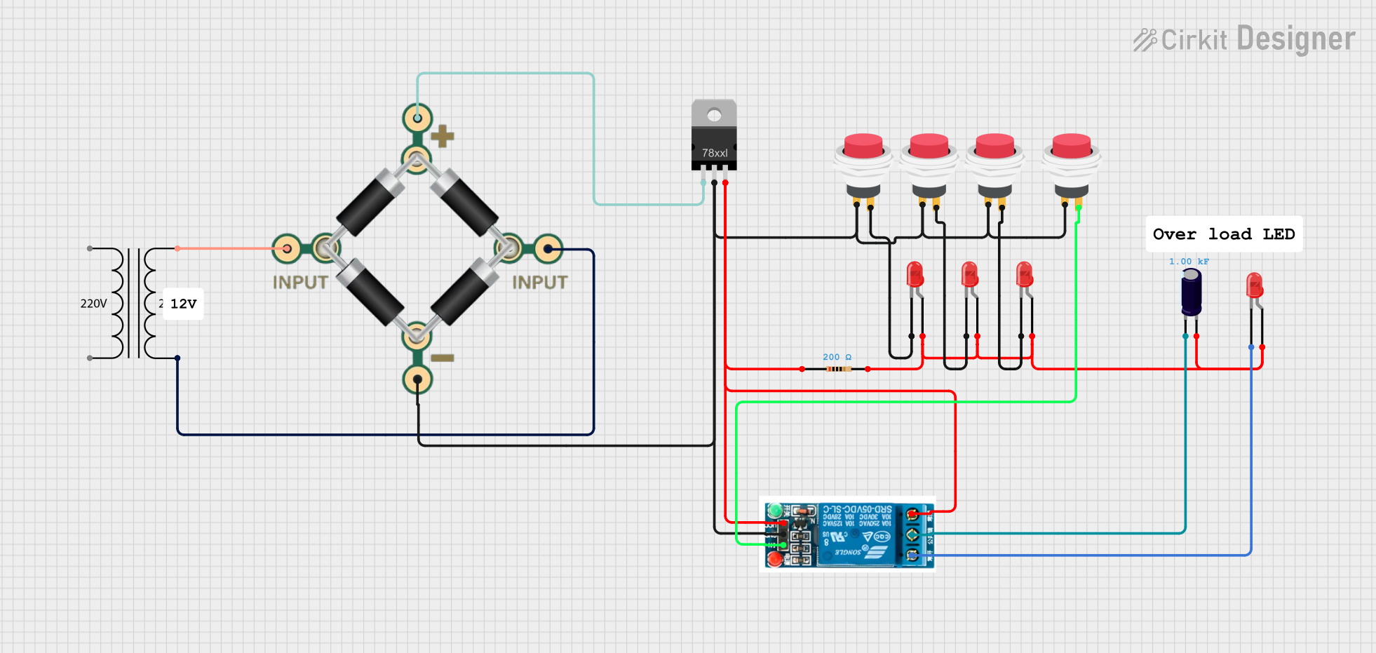
This circuit consists of multiple LEDs, resistors, push switches, a power transformer, a bridge rectifier, a voltage regulator, a relay, and an electrolytic capacitor. The circuit is designed to control the LEDs using push switches and a relay, with power regulation provided by the transformer, bridge rectifier, and voltage regulator.
Component List
LED: Two Pin (red)
- Pins: cathode, anode
- Description: Red LED
- Purpose: Indication
Resistor
- Pins: pin1, pin2
- Description: 200 Ohms resistor
- Purpose: Current limiting
- Properties:
- Resistance: 200 Ohms
2Pin Push Switch
- Pins: Input +, Output +
- Description: Push button switch
- Purpose: User input
BRIDGE - 1N4007
- Pins: 1 INPUT, 2 INPUT, + PIN, - PIN
- Description: Bridge rectifier
- Purpose: AC to DC conversion
Power Transformer (220V to 24V)
- Pins: 2 - Primary, 1 - Primary, 3 - Secondary, 4 - Secondary
- Description: Step-down transformer
- Purpose: Voltage conversion
Voltage Regulator
- Pins: IN, GND, OUT
- Description: Voltage regulator
- Purpose: Voltage stabilization
5v relay
- Pins: Normally Open, Common terminal, Normally Closed, In, GND, VCC
- Description: Relay
- Purpose: Switching
Electrolytic Capacitor
- Pins: -, +
- Description: 1000 Farads capacitor
- Purpose: Smoothing
- Properties:
- Capacitance: 1000 Farads
Wiring Details
LED: Two Pin (red)
LED 1
- Cathode: Connected to Output + of Push Switch 1
- Anode: Connected to Anode of LED 2, Anode of LED 3, Anode of LED 4, Anode of LED 5, Pin2 of Resistor, and + of Electrolytic Capacitor
LED 2
- Cathode: Connected to Output + of Push Switch 2
- Anode: Connected to Anode of LED 1, Anode of LED 3, Anode of LED 4, Anode of LED 5, Pin2 of Resistor, and + of Electrolytic Capacitor
LED 3
- Cathode: Connected to Output + of Push Switch 3
- Anode: Connected to Anode of LED 1, Anode of LED 2, Anode of LED 4, Anode of LED 5, Pin2 of Resistor, and + of Electrolytic Capacitor
LED 4
- Cathode: Connected to Normally Open of Relay
- Anode: Connected to Anode of LED 1, Anode of LED 2, Anode of LED 3, Anode of LED 5, Pin2 of Resistor, and + of Electrolytic Capacitor
LED 5
- Cathode: Connected to Output + of Push Switch 4
- Anode: Connected to Anode of LED 1, Anode of LED 2, Anode of LED 3, Anode of LED 4, Pin2 of Resistor, and + of Electrolytic Capacitor
Resistor
- Pin1: Connected to OUT of Voltage Regulator, Normally Closed of Relay, and VCC of Relay
- Pin2: Connected to Anode of LED 1, Anode of LED 2, Anode of LED 3, Anode of LED 4, Anode of LED 5, and + of Electrolytic Capacitor
2Pin Push Switch
Push Switch 1
- Input +: Connected to GND of Voltage Regulator, Input + of Push Switch 2, Input + of Push Switch 3, Input + of Push Switch 4, GND of Relay, and - PIN of Bridge Rectifier
- Output +: Connected to Cathode of LED 1 and Cathode of LED 2
Push Switch 2
- Input +: Connected to GND of Voltage Regulator, Input + of Push Switch 1, Input + of Push Switch 3, Input + of Push Switch 4, GND of Relay, and - PIN of Bridge Rectifier
- Output +: Connected to In of Relay
Push Switch 3
- Input +: Connected to GND of Voltage Regulator, Input + of Push Switch 1, Input + of Push Switch 2, Input + of Push Switch 4, GND of Relay, and - PIN of Bridge Rectifier
- Output +: Connected to Cathode of LED 3
Push Switch 4
- Input +: Connected to GND of Voltage Regulator, Input + of Push Switch 1, Input + of Push Switch 2, Input + of Push Switch 3, GND of Relay, and - PIN of Bridge Rectifier
- Output +: Connected to Cathode of LED 5
BRIDGE - 1N4007
- 1 INPUT: Connected to 3 - Secondary of Power Transformer
- 2 INPUT: Connected to 4 - Secondary of Power Transformer
-
- PIN: Connected to IN of Voltage Regulator
-
- PIN: Connected to GND of Voltage Regulator, Input + of Push Switch 1, Input + of Push Switch 2, Input + of Push Switch 3, Input + of Push Switch 4, and GND of Relay
Power Transformer (220V to 24V)
- 3 - Secondary: Connected to 1 INPUT of Bridge Rectifier
- 4 - Secondary: Connected to 2 INPUT of Bridge Rectifier
Voltage Regulator
- IN: Connected to + PIN of Bridge Rectifier
- GND: Connected to - PIN of Bridge Rectifier, Input + of Push Switch 1, Input + of Push Switch 2, Input + of Push Switch 3, Input + of Push Switch 4, and GND of Relay
- OUT: Connected to Pin1 of Resistor, Normally Closed of Relay, and VCC of Relay
5v relay
- Normally Open: Connected to Cathode of LED 4
- Common terminal: Connected to - of Electrolytic Capacitor
- Normally Closed: Connected to OUT of Voltage Regulator and Pin1 of Resistor
- In: Connected to Output + of Push Switch 2
- GND: Connected to GND of Voltage Regulator, Input + of Push Switch 1, Input + of Push Switch 2, Input + of Push Switch 3, Input + of Push Switch 4, and - PIN of Bridge Rectifier
- VCC: Connected to OUT of Voltage Regulator and Pin1 of Resistor
Electrolytic Capacitor
- -: Connected to Common terminal of Relay
- +: Connected to Anode of LED 1, Anode of LED 2, Anode of LED 3, Anode of LED 4, Anode of LED 5, and Pin2 of Resistor
Code
No microcontroller code is provided for this circuit.