Cirkit Designer
Your all-in-one circuit design IDE
Home /
Project Documentation
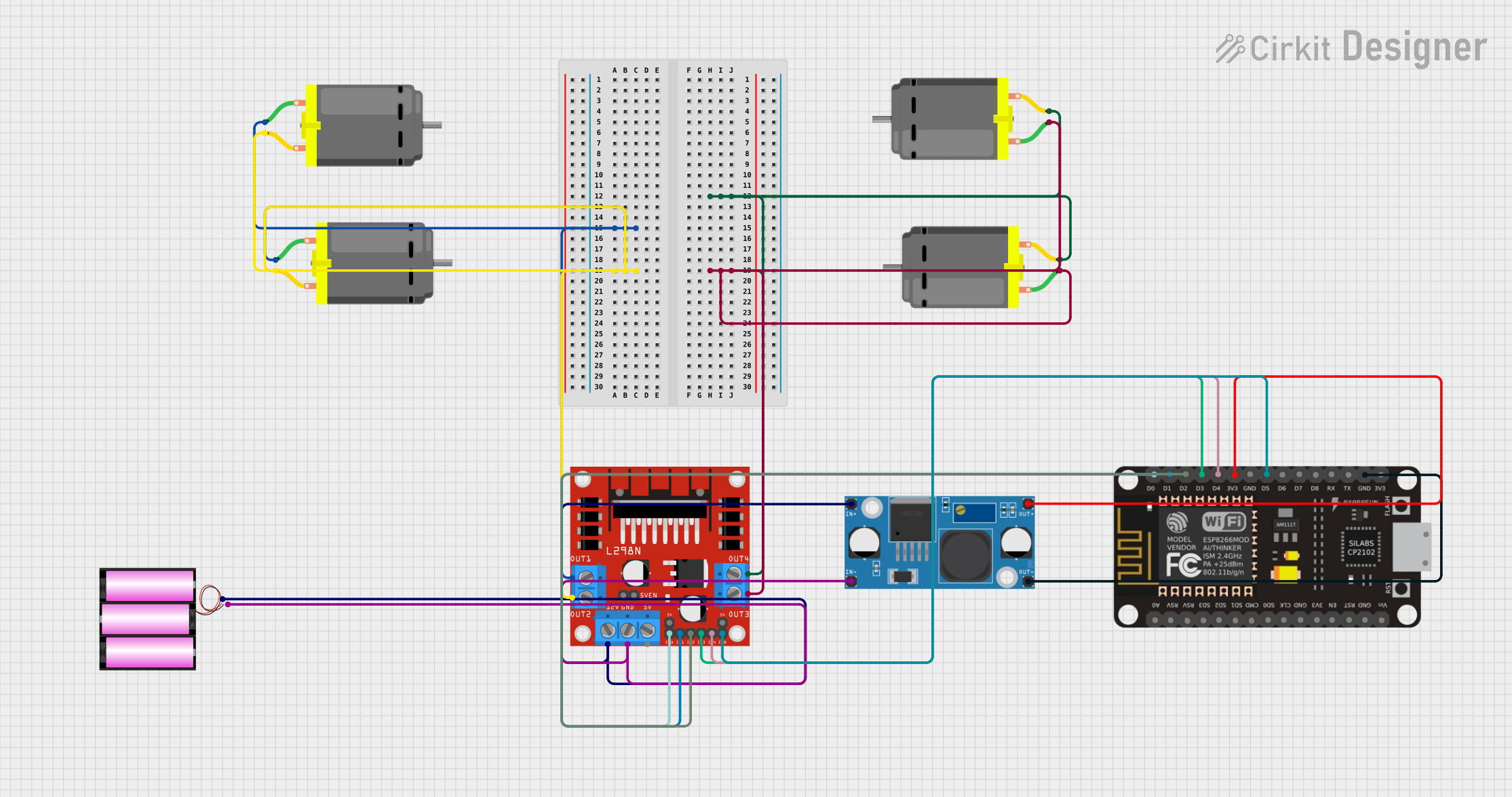
Wi-Fi Controlled Quad DC Motor Driver System
Circuit Documentation
Summary
This circuit is designed to control multiple DC motors using an ESP-8266 microcontroller and an L298N DC motor driver. The ESP-8266 provides the control signals to the L298N driver, which in turn drives the motors. A buck converter (LM2956) steps down the voltage from a 12V battery to supply the ESP-8266. The motors are connected in pairs to the L298N driver outputs.
Component List
ESP-8266 Controller
- Microcontroller with WiFi capability.
- Pins: A0, RSV, SD3, SD5, SD1, CMD, D0, D1, D2, D3, D4, 3V3, GND, D5, D6, SD0, CLK, RST, EN, D7, D8, RX, TX, Vin, 5V.
DC Motor
- Electric motor that converts DC electrical power into mechanical power.
- Pins: pin 1, pin 2.
LM2956 Buck Converter DC-DC
- A buck converter that steps down voltage from a higher level to a lower level.
- Pins: OUT+, OUT-, IN+, IN-.
Battery 12V
- A 12V power source for the circuit.
- Pins: +, -.
L298N DC Motor Driver
- A dual H-bridge motor driver that can drive two DC motors.
- Pins: OUT1, OUT2, 12V, GND, 5V, OUT3, OUT4, 5V-ENA-JMP-I, 5V-ENA-JMP-O, +5V-J1, +5V-J2, ENA, IN1, IN2, IN3, IN4, ENB.
Wiring Details
ESP-8266 Controller
- D0 -> L298N DC motor driver ENA
- D1 -> L298N DC motor driver IN1
- D2 -> L298N DC motor driver IN2
- D3 -> L298N DC motor driver IN3
- D4 -> L298N DC motor driver IN4
- 3V3 -> LM2956 Buck Converter DC-DC OUT+
- GND -> LM2956 Buck Converter DC-DC OUT-
- D5 -> L298N DC motor driver ENB
DC Motors
- Motor 1: pin 1 -> L298N DC motor driver OUT3, pin 2 -> L298N DC motor driver OUT4
- Motor 2: pin 1 -> L298N DC motor driver OUT1, pin 2 -> L298N DC motor driver OUT2
LM2956 Buck Converter DC-DC
- IN+ -> Battery 12V +, L298N DC motor driver 12V
- IN- -> Battery 12V -, L298N DC motor driver GND
- OUT+ -> ESP-8266 Controller 3V3
- OUT- -> ESP-8266 Controller GND
Battery 12V
- -> LM2956 Buck Converter DC-DC IN+
- -> LM2956 Buck Converter DC-DC IN-
L298N DC Motor Driver
- OUT1 -> DC Motor 2 pin 1
- OUT2 -> DC Motor 2 pin 2
- OUT3 -> DC Motor 1 pin 1
- OUT4 -> DC Motor 1 pin 2
- 12V -> LM2956 Buck Converter DC-DC IN+
- GND -> LM2956 Buck Converter DC-DC IN-
- ENA -> ESP-8266 Controller D0
- IN1 -> ESP-8266 Controller D1
- IN2 -> ESP-8266 Controller D2
- IN3 -> ESP-8266 Controller D3
- IN4 -> ESP-8266 Controller D4
- ENB -> ESP-8266 Controller D5
Documented Code
No code has been provided for the ESP-8266 microcontroller. The code would typically initialize the GPIO pins connected to the L298N motor driver and set up WiFi communication if needed. It would also include the main control loop to drive the motors based on the received commands.