Cirkit Designer
Your all-in-one circuit design IDE
Home /
Project Documentation
Arduino UNO-Based Environmental Monitoring System with pH, Temperature, and Turbidity Sensors
Circuit Documentation
Summary
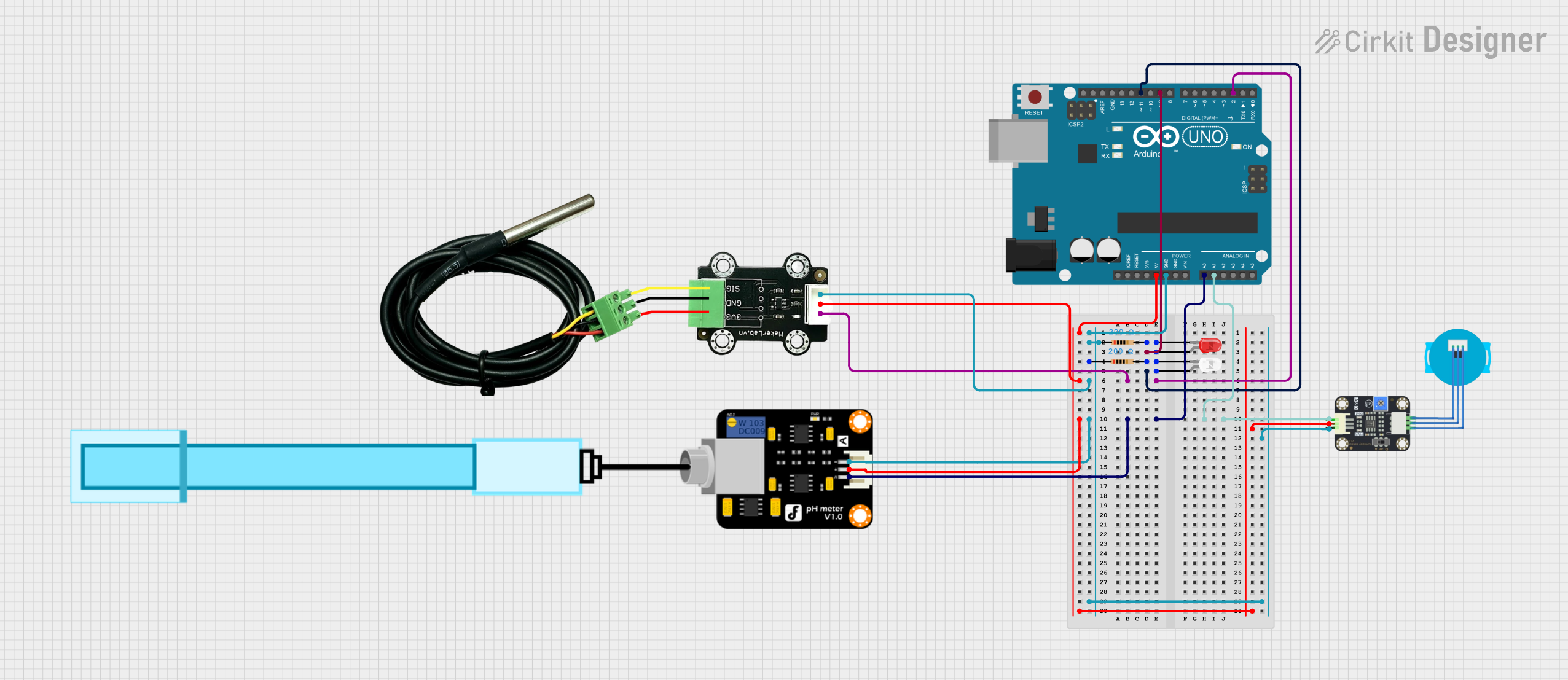
This document provides a detailed overview of a circuit that includes various sensors, LEDs, resistors, and an Arduino UNO microcontroller. The circuit is designed to measure pH, temperature, and turbidity, and it uses LEDs to indicate certain conditions. The Arduino UNO serves as the central controller, interfacing with all the sensors and LEDs.
Component List
PH Meter
- Description: Measures the pH level of a solution.
- Pins: Signal, VCC, GND
MKE-S15 DS18B20 Waterproof Temperature Sensor
- Description: Measures the temperature of a solution.
- Pins: SIG, 5V, GND
Arduino UNO
- Description: Microcontroller used to interface with sensors and control LEDs.
- Pins: UNUSED, IOREF, Reset, 3.3V, 5V, GND, Vin, A0, A1, A2, A3, A4, A5, SCL, SDA, AREF, D13, D12, D11, D10, D9, D8, D7, D6, D5, D4, D3, D2, D1, D0
Resistor (200 Ohms)
- Description: Limits current to prevent damage to components.
- Pins: pin1, pin2
- Properties: Resistance: 200 Ohms
LED: Two Pin (red)
- Description: Emits red light when powered.
- Pins: cathode, anode
LED: Two Pin (white)
- Description: Emits white light when powered.
- Pins: cathode, anode
Turbidity Sensor
- Description: Measures the turbidity (cloudiness) of a solution.
- Pins: OUT, VCC, GND
Wiring Details
PH Meter
- Signal connected to A0 on Arduino UNO
- VCC connected to 5V on Arduino UNO
- GND connected to GND on Arduino UNO
MKE-S15 DS18B20 Waterproof Temperature Sensor
- SIG connected to D2 on Arduino UNO
- 5V connected to 5V on Arduino UNO
- GND connected to GND on Arduino UNO
Arduino UNO
- D9 connected to anode of red LED
- D11 connected to anode of white LED
- D2 connected to SIG of Temperature Sensor
- A0 connected to Signal of PH Meter
- A1 connected to OUT of Turbidity Sensor
- 5V connected to 5V of Temperature Sensor, PH Meter, and Turbidity Sensor
- GND connected to GND of Temperature Sensor, PH Meter, Turbidity Sensor, and pin1 of both resistors
Resistor (200 Ohms)
- pin1 connected to GND on Arduino UNO
- pin2 connected to cathode of red LED
Resistor (200 Ohms)
- pin1 connected to GND on Arduino UNO
- pin2 connected to cathode of white LED
LED: Two Pin (red)
- anode connected to D9 on Arduino UNO
- cathode connected to pin2 of a 200 Ohm resistor
LED: Two Pin (white)
- anode connected to D11 on Arduino UNO
- cathode connected to pin2 of a 200 Ohm resistor
Turbidity Sensor
- OUT connected to A1 on Arduino UNO
- VCC connected to 5V on Arduino UNO
- GND connected to GND on Arduino UNO
Documented Code
Arduino UNO Code
void setup() {
  // put your setup code here, to run once:

}

void loop() {
  // put your main code here, to run repeatedly:

}
This code is a basic template for the Arduino UNO. The setup function is used to initialize any settings or configurations, and the loop function contains the main code that runs repeatedly. You can add your specific logic for reading sensor data and controlling the LEDs within these functions.