Cirkit Designer
Your all-in-one circuit design IDE
Home /
Project Documentation
Alcohol Detection System with Visual and Audible Alerts

Circuit Documentation
Summary
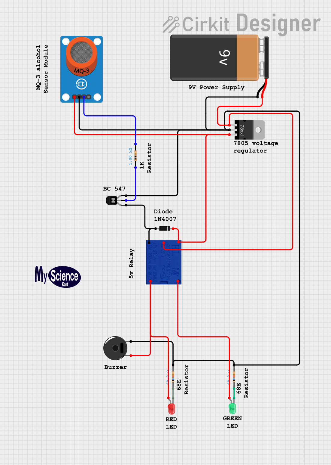
The circuit described by the provided inputs is a control circuit that utilizes a relay to switch between two different outputs based on the signal from an MQ-3 alcohol sensor. The circuit includes a voltage regulator to ensure stable operation, a transistor to amplify the sensor's signal, and protection diodes. It also features visual indicators in the form of LEDs and an audible indicator using a piezo buzzer.
Component List
Relay 5V
- Description: A 5V relay used to switch between two different outputs.
- Pins: COM (Common), COIL 1, COIL 2, NO (Normally Open), NC (Normally Closed)
Resistor (1k Ohms)
- Description: A resistor with a resistance of 1000 Ohms.
- Pins: pin1, pin2
Voltage Regulator
- Description: A voltage regulator to maintain a stable voltage level for the circuit.
- Pins: IN (Input), GND (Ground), OUT (Output)
9V Battery
- Description: A 9V battery providing the power source for the circuit.
- Pins: + (Positive), - (Negative)
NPN Transistor (EBC)
- Description: An NPN transistor used to amplify the signal from the MQ-3 sensor.
- Pins: emitter, base, collector
Diode
- Description: A diode used for protecting the circuit from reverse voltage spikes.
- Pins: cathode, anode
Piezo Buzzer
- Description: An audible indicator that can be triggered by the circuit.
- Pins: pin 1, pin 2
MQ-3 Breakout
- Description: An alcohol sensor that outputs a digital signal.
- Pins: VCC (Power), GND (Ground), DO (Digital Output), AO (Analog Output)
LED: Two Pin (red)
- Description: A red LED used as a visual indicator.
- Pins: cathode, anode
LED: Two Pin (green)
- Description: A green LED used as a visual indicator.
- Pins: cathode, anode
Resistor (68 Ohms)
- Description: A resistor with a resistance of 68 Ohms, likely used to limit current to the LEDs.
- Pins: pin1, pin2
Wiring Details
Relay 5V
- COM connected to Voltage Regulator OUT
- COIL 1 connected to NPN Transistor emitter
- COIL 2 connected to Voltage Regulator OUT
- NO connected to LED: Two Pin (green) anode
- NC connected to LED: Two Pin (red) anode and Piezo Buzzer pin 1
Resistor (1k Ohms)
- pin1 connected to NPN Transistor base
- pin2 connected to MQ-3 Breakout DO
Voltage Regulator
- IN connected to 9V Battery +
- GND connected to 9V Battery -, Piezo Buzzer pin 2, MQ-3 Breakout GND, and common ground for other components
- OUT connected to Relay 5V COIL 2 and Diode cathode
9V Battery
- connected to Voltage Regulator IN
- connected to common ground
NPN Transistor (EBC)
- emitter connected to Relay 5V COIL 1
- base connected to Resistor (1k Ohms) pin1
- collector connected to common ground
Diode
- cathode connected to Voltage Regulator OUT
- anode connected to NPN Transistor emitter
Piezo Buzzer
- pin 1 connected to Relay 5V NC
- pin 2 connected to common ground
MQ-3 Breakout
- VCC connected to Voltage Regulator OUT
- GND connected to common ground
- DO connected to Resistor (1k Ohms) pin2
LED: Two Pin (red)
- anode connected to Relay 5V NC
- cathode connected to Resistor (68 Ohms) pin1
LED: Two Pin (green)
- anode connected to Relay 5V NO
- cathode connected to Resistor (68 Ohms) pin1
Resistor (68 Ohms)
- pin1 connected to LED: Two Pin (red) cathode and LED: Two Pin (green) cathode
- pin2 connected to common ground
Documented Code
No code was provided for any microcontrollers in the circuit. If there are microcontrollers involved, please provide the relevant code for documentation.