
Arduino-Controlled Robotics Platform with Ultrasonic Sensing and Dual Motor Drivers
View and Edit Project In Cirkit Designer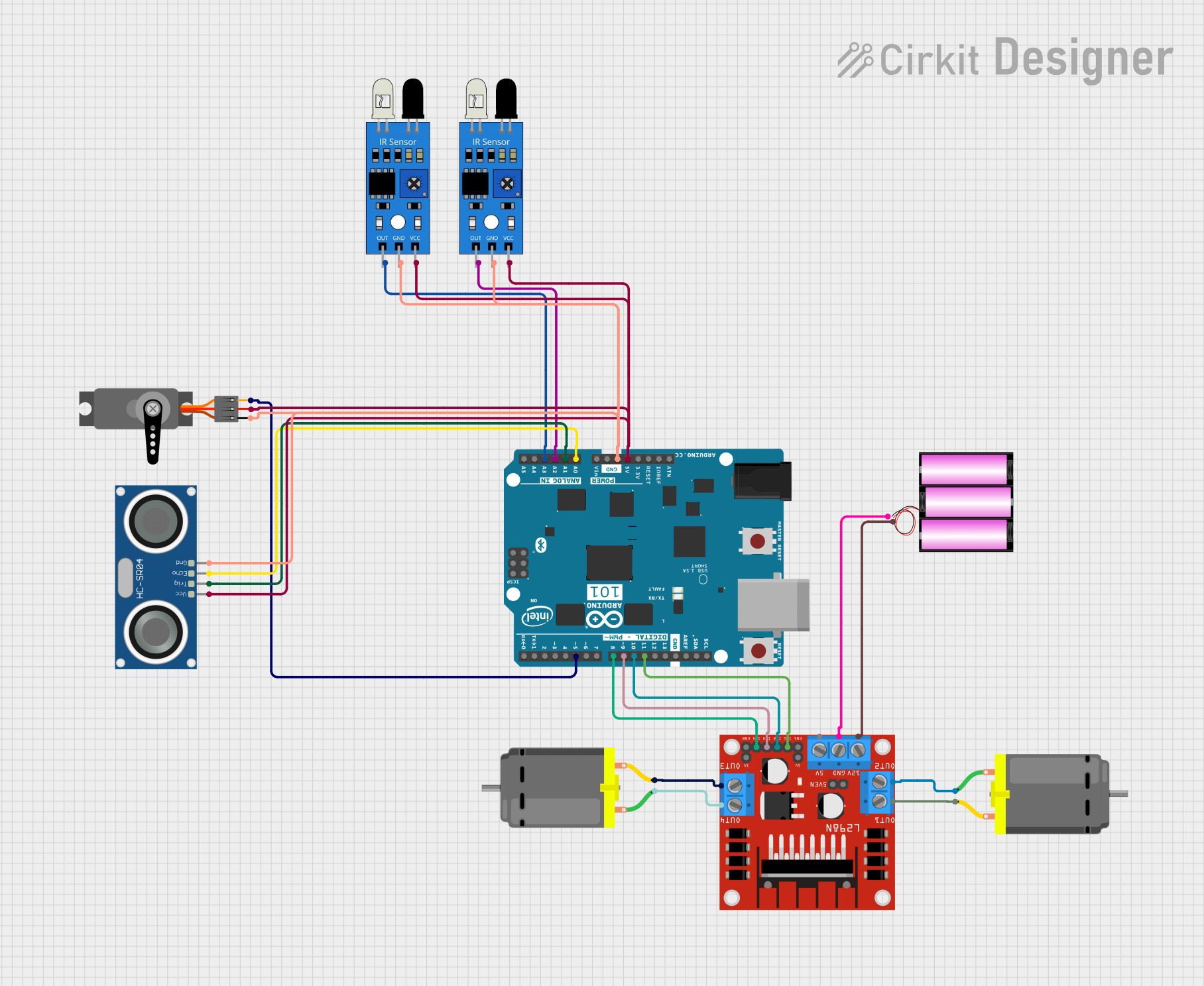
Circuit Documentation
Summary
This circuit is designed to control two DC motors using an L298N motor driver, interfaced with an Arduino 101 microcontroller. The circuit also includes a servo motor, two IR sensors, and an HC-SR04 ultrasonic sensor for distance measurement. The power supply for the motor driver is provided by a 12V battery. The Arduino 101 controls the motors and reads signals from the sensors to perform various tasks based on the programmed logic. The circuit is suitable for applications such as robotics, where motor control and environmental sensing are required.
Component List
Arduino 101
- Microcontroller board based on the Intel Curie
- Provides PWM outputs and digital I/O pins
- Analog inputs for sensor interfacing
- I2C and SPI communication
- 3.3V and 5V power output
L298N DC Motor Driver
- Dual H-bridge motor driver
- Capable of driving two DC motors or one stepper motor
- Provides 5V output for external components
- Supports PWM for speed control
Servo
- Standard servo motor for precise angular control
- Requires PWM signal for operation
HC-SR04 Ultrasonic Sensor
- Ultrasonic distance measuring sensor
- Uses echo and trigger pins for distance calculation
DC Motor (x2)
- Standard DC motors for rotational motion
- Driven by the L298N motor driver
IR Sensor (x2)
- Infrared sensors for object detection
- Outputs a digital signal when an object is detected
Battery 12V
- Provides power to the L298N motor driver and motors
Wiring Details
Arduino 101
D11 PWM/MOSIconnected to L298NIN1D10 PWM/SSconnected to L298NIN2D9 PWMconnected to L298NIN3D8connected to L298NIN4D5 PWMconnected to ServoPWM5Vconnected to ServoVCC, both IR sensorsvcc, and HC-SR04VCCGNDconnected to ServoGND, both IR sensorsgnd, and HC-SR04GNDA0connected to HC-SR04ECHOA1connected to HC-SR04TRIGA2connected to first IR sensoroutA3connected to second IR sensorout
L298N DC Motor Driver
IN1toIN4controlled by Arduino 101OUT1andOUT2connected to first DC MotorOUT3andOUT4connected to second DC Motor12VandGNDconnected to 12V Battery
Servo
PWMsignal from Arduino 101VCCandGNDconnected to Arduino 101 power outputs
HC-SR04 Ultrasonic Sensor
VCCandGNDconnected to Arduino 101 power outputsECHOandTRIGconnected to Arduino 101 analog inputs
DC Motors
- Each motor connected to two outputs from L298N
IR Sensors
outconnected to Arduino 101 analog inputsvccandgndconnected to Arduino 101 power outputs
Battery 12V
- Provides power to L298N
12VandGND
Documented Code
No code was provided for the microcontroller. The expected code should handle the initialization of the pins, setup of PWM for motor and servo control, and reading of sensor inputs to make decisions based on sensor data.
Please note that the actual functionality of the circuit will depend on the specific code uploaded to the Arduino 101. The code should be written to initialize the pins according to the wiring details, generate PWM signals for motor and servo control, and read the sensor outputs to perform the desired actions.