
ESP32-Controlled Ultrasonic Distance Measurement with I2C LCD Display
View and Edit Project In Cirkit Designer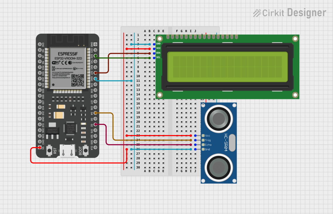
Circuit Documentation
Summary of the Circuit
This circuit integrates an I2C LCD 16x2 screen, an HC-SR04 ultrasonic sensor, and an ESP32 microcontroller. The LCD screen is used for displaying information, the ultrasonic sensor is for measuring distances, and the ESP32 serves as the central processing unit that controls the sensor, processes the data, and updates the display. The components are interconnected through I2C communication lines and share a common power supply and ground.
Component List
I2C LCD 16x2 Screen
- Description: A 16x2 character LCD display that uses the I2C communication protocol.
- Pins: SCL, SDA, VCC (5V), GND, VDD, VO, RS, RW, E, D0, D1, D2, D3, D4, D5, D6, D7, BLA, BLK
HC-SR04 Ultrasonic Sensor
- Description: An ultrasonic ranging module that provides 2cm to 400cm non-contact measurement functionality.
- Pins: VCC, TRIG, ECHO, GND
ESP32 - 38 pins
- Description: A powerful microcontroller with Wi-Fi and Bluetooth capabilities, suitable for a variety of applications.
- Pins: 3V3, EN, SP, SN, G34, G35, G32, G33, G25, G26, G27, G14, G12, GND, G13, SD2, SD3, CMD, 5V, G23, G22, TXD, RXD, G21, G19, G18, G5, G17, G16, G4, G0, G2, G15, SD1, SD0, CLK
Wiring Details
I2C LCD 16x2 Screen
- VCC (5V): Connected to the 5V power supply from the ESP32.
- GND: Connected to the common ground.
- SDA: Connected to GPIO 21 (G21) on the ESP32 for I2C data.
- SCL: Connected to GPIO 22 (G22) on the ESP32 for I2C clock.
HC-SR04 Ultrasonic Sensor
- VCC: Connected to the 5V power supply from the ESP32.
- GND: Connected to the common ground.
- TRIG: Connected to GPIO 4 (G4) on the ESP32 to trigger the ultrasonic pulse.
- ECHO: Connected to GPIO 2 (G2) on the ESP32 to receive the echo signal.
ESP32 - 38 pins
- 5V: Provides power to the I2C LCD screen and the HC-SR04 ultrasonic sensor.
- GND: Common ground for the circuit.
- G21 (SDA): Connected to the SDA pin of the I2C LCD screen.
- G22 (SCL): Connected to the SCL pin of the I2C LCD screen.
- G4: Connected to the TRIG pin of the HC-SR04 ultrasonic sensor.
- G2: Connected to the ECHO pin of the HC-SR04 ultrasonic sensor.
Documented Code
No code has been provided for the microcontroller. The documentation of the code would typically include a description of the functionality, setup and loop functions, and any functions or libraries used to control the I2C LCD screen and read data from the HC-SR04 ultrasonic sensor. Since no code is available, this section cannot be completed at this time.