
Arduino UNO-Based Line Following Robot with NRF24L01 Wireless Control and Battery Power
View and Edit Project In Cirkit Designer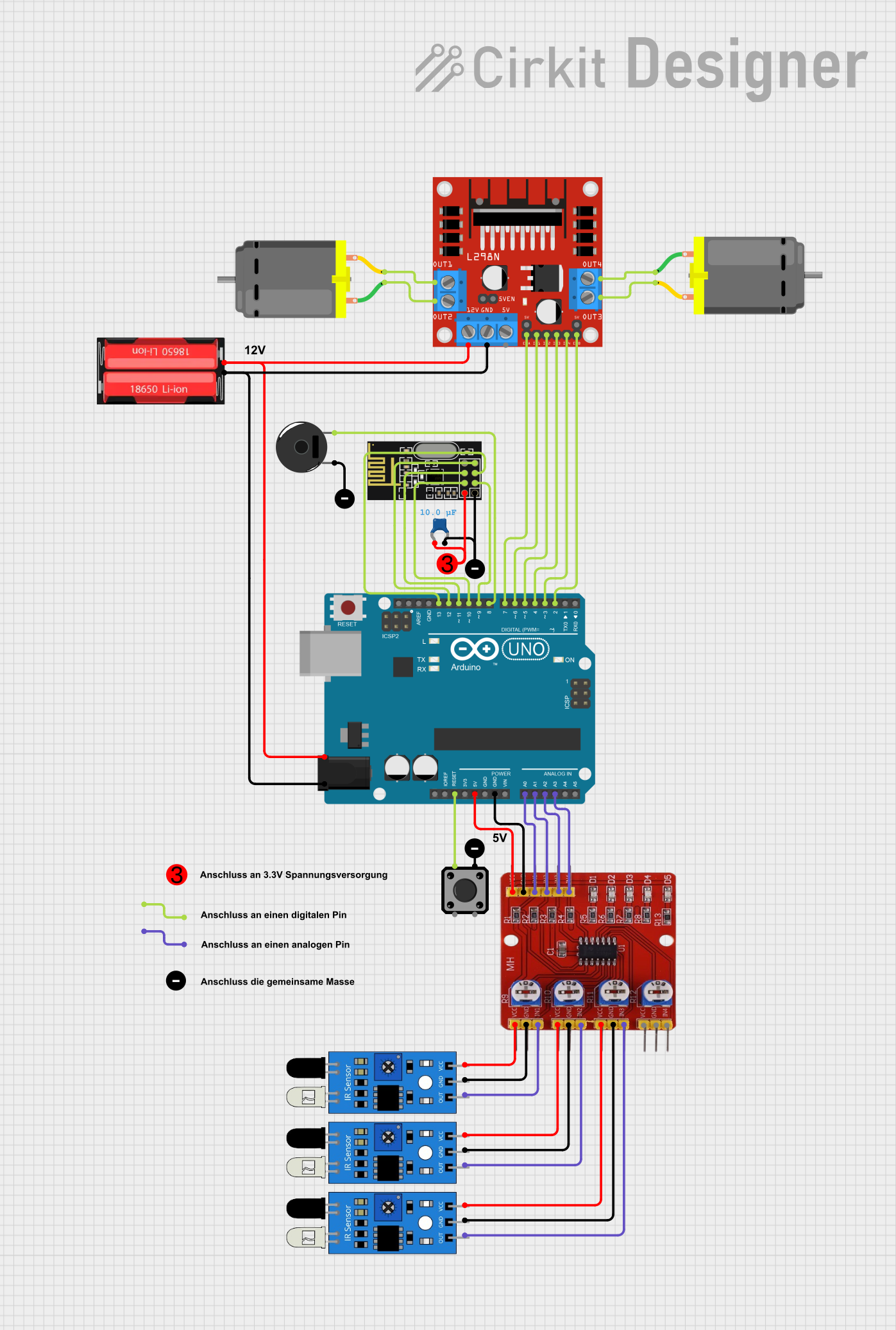
Circuit Documentation
Summary
This document provides a detailed overview of a circuit that includes an Arduino UNO microcontroller, an NRF24L01 wireless module, a 4 Channel Infrared Tracing Module, multiple IR sensors, a tactile switch button, a piezo buzzer, DC motors, and an L298N DC motor driver. The circuit is powered by a 18650 Li-Ion battery. The document includes a component list, wiring details, and the embedded code used in the microcontroller.
Component List
NRF24L01
- Description: Wireless transceiver module
- Pins: IRQ (not used), MOSI, CSN, VCC (3V), GND, CE, SCK, MISO
4 Channel Infrared Tracing Module
- Description: Module for detecting infrared signals
- Pins: VCC, GND, IN1, IN2, IN3, IN4
Tactile Switch Buttons - 12mm Square
- Description: Push button switch
- Pins: 3, 1, 4, 2
Arduino UNO
- Description: Microcontroller board based on the ATmega328P
- Pins: UNUSED, IOREF, Reset, 3.3V, 5V, GND, Vin, A0, A1, A2, A3, A4, A5, SCL, SDA, AREF, D13, D12, D11, D10, D9, D8, D7, D6, D5, D4, D3, D2, D1, D0
DC Motor
- Description: Direct current motor
- Pins: pin 1, pin 2
L298N DC Motor Driver
- Description: Dual H-Bridge motor driver
- Pins: OUT1, OUT2, 12V, GND, 5V, OUT3, OUT4, 5V-ENA-JMP-I, 5V-ENA-JMP-O, +5V-J1, +5V-J2, ENA, IN1, IN2, IN3, IN4, ENB
IR Sensor
- Description: Infrared sensor
- Pins: out, gnd, vcc
18650 Li-Ion
- Description: Lithium-ion rechargeable battery
- Pins: Positive, Negative
Ceramic Capacitor
- Description: Capacitor with a capacitance of 0.00001 Farads
- Pins: pin0, pin1
Piezo Buzzer
- Description: Buzzer for sound output
- Pins: pin 1, pin 2
Erde
- Description: Ground connection
- Pins: GND
2 Anschlüsse
- Description: Connector with two terminals
- Pins: GND, VCC
Wiring Details
NRF24L01
- MOSI connected to Arduino UNO D11
- CSN connected to Arduino UNO D10
- VCC (3V) connected to 3V
- GND connected to Erde GND
- CE connected to Arduino UNO D9
- SCK connected to Arduino UNO D13
- MISO connected to Arduino UNO D12
4 Channel Infrared Tracing Module
- IN1 connected to IR Sensor out
- GND connected to IR Sensor gnd
- VCC connected to IR Sensor vcc
- IN2 connected to IR Sensor out
- GND connected to IR Sensor gnd
- VCC connected to IR Sensor vcc
- IN3 connected to IR Sensor out
- GND connected to IR Sensor gnd
- VCC connected to IR Sensor vcc
- IN4 connected to Arduino UNO A3
- VCC connected to Arduino UNO 5V
- GND connected to Arduino UNO GND
- IN1 connected to Arduino UNO A0
- IN2 connected to Arduino UNO A1
- IN3 connected to Arduino UNO A2
Tactile Switch Buttons - 12mm Square
- Pin 1 connected to Arduino UNO Reset
- Pin 2 connected to Erde GND
DC Motor
- Pin 1 connected to L298N DC Motor Driver OUT2
- Pin 2 connected to L298N DC Motor Driver OUT1
- Pin 1 connected to L298N DC Motor Driver OUT4
- Pin 2 connected to L298N DC Motor Driver OUT3
L298N DC Motor Driver
- OUT1 connected to DC Motor pin 2
- OUT2 connected to DC Motor pin 1
- 12V connected to 18650 Li-Ion Positive
- GND connected to 18650 Li-Ion Negative
- OUT3 connected to DC Motor pin 2
- OUT4 connected to DC Motor pin 1
- ENA connected to Arduino UNO D7
- IN1 connected to Arduino UNO D6
- IN2 connected to Arduino UNO D5
- IN3 connected to Arduino UNO D4
- IN4 connected to Arduino UNO D3
- ENB connected to Arduino UNO D2
IR Sensor
- out connected to 4 Channel Infrared Tracing Module IN1
- gnd connected to 4 Channel Infrared Tracing Module GND
- vcc connected to 4 Channel Infrared Tracing Module VCC
- out connected to 4 Channel Infrared Tracing Module IN2
- gnd connected to 4 Channel Infrared Tracing Module GND
- vcc connected to 4 Channel Infrared Tracing Module VCC
- out connected to 4 Channel Infrared Tracing Module IN3
- gnd connected to 4 Channel Infrared Tracing Module GND
- vcc connected to 4 Channel Infrared Tracing Module VCC
18650 Li-Ion
- Positive connected to L298N DC Motor Driver 12V
- Negative connected to L298N DC Motor Driver GND
Ceramic Capacitor
- pin0 connected to 3V
- pin1 connected to Erde GND
Piezo Buzzer
- Pin 2 connected to Arduino UNO D8
- Pin 1 connected to Erde GND
2 Anschlüsse
- GND connected to 2 Anschlüsse VCC
- VCC connected to 2 Anschlüsse GND
Code
Arduino UNO Code (sketch.ino)
void setup() {
  // put your setup code here, to run once:

}

void loop() {
  // put your main code here, to run repeatedly:

}
This concludes the documentation for the circuit. Each component and its connections have been detailed, and the code for the Arduino UNO microcontroller has been provided.