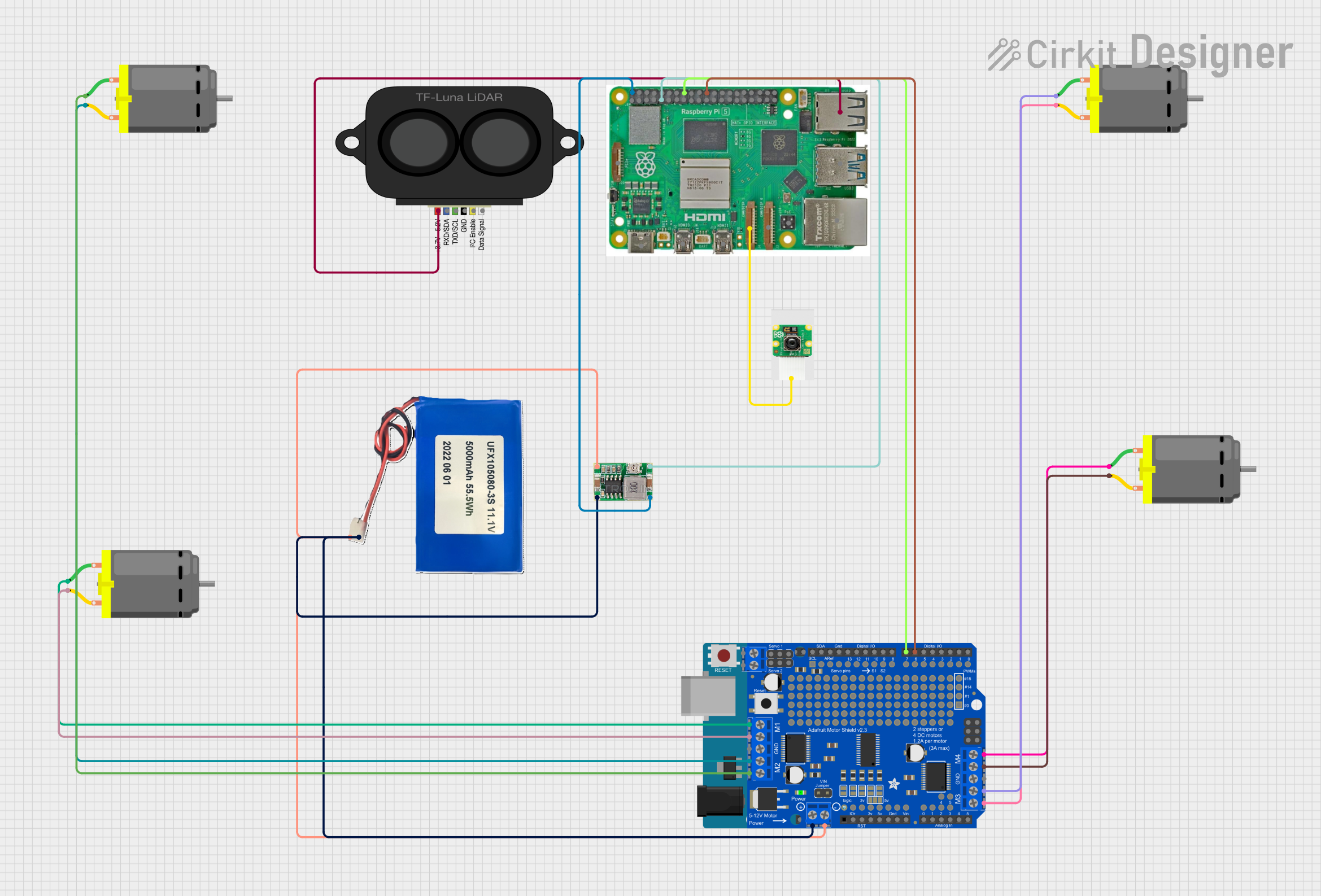
Raspberry Pi 5 Controlled Robotic Vehicle with LIDAR and Camera Module

Circuit Documentation
Summary
This circuit integrates a variety of components including a Raspberry Pi 5, a Raspberry Pi Camera Module 2, a TF LUNA LIDAR sensor, a Mini 360 Buck Converter, multiple DC Motors, an Arduino UNO microcontroller, a Li-ion 5000mAh battery, and an Adafruit Motor, Stepper & Servo Shield. The circuit is designed to interface sensors and motors with the Raspberry Pi 5 and Arduino UNO, providing a platform for applications such as robotics, automation, or surveillance systems.
Component List
Raspberry Pi Camera Module 2
- A camera module designed to work with Raspberry Pi boards, capable of capturing high-quality images and video.
TF LUNA LIDAR
- A compact time-of-flight (ToF) sensor that provides accurate distance measurements.
Mini 360 Buck Converter
- A voltage step-down (buck) converter that efficiently reduces input voltage to a lower output voltage.
DC Motors
- Four identical motors used for driving mechanical components such as wheels or actuators.
Arduino UNO
- A microcontroller board based on the ATmega328P, widely used for building digital devices and interactive objects.
Raspberry Pi 5
- A powerful single-board computer with a broad range of connectivity options and GPIO pins for interfacing with various peripherals.
Li-ion 5000mAh Battery
- A rechargeable lithium-ion battery providing a power source for the circuit.
Adafruit Motor, Stepper & Servo Shield
- An add-on board for Arduino UNO that allows for the control of multiple motors and servos.
Wiring Details
Raspberry Pi Camera Module 2
- Camera Cable connected to Camera 1 on Raspberry Pi 5.
TF LUNA LIDAR
- Power connected to USB 2.0 on Raspberry Pi 5.
Mini 360 Buck Converter
- OUT+ connected to 5V on Raspberry Pi 5.
- OUT- connected to GND on Raspberry Pi 5.
- IN+ connected to 11.1V on Li-ion 5000mAh Battery.
- IN- connected to GND on Li-ion 5000mAh Battery.
DC Motors
- Motor 1: pin 1 connected to M4A, pin 2 connected to M4B on Adafruit Motor, Stepper & Servo Shield.
- Motor 2: pin 1 connected to M3A, pin 2 connected to M3B on Adafruit Motor, Stepper & Servo Shield.
- Motor 3: pin 1 connected to M2A, pin 2 connected to M2B on Adafruit Motor, Stepper & Servo Shield.
- Motor 4: pin 1 connected to M1A, pin 2 connected to M1B on Adafruit Motor, Stepper & Servo Shield.
Adafruit Motor, Stepper & Servo Shield
- D7 connected to GPIO 23 on Raspberry Pi 5.
- D6 connected to GPIO 25 on Raspberry Pi 5.
- VMOTOR connected to 11.1V on Li-ion 5000mAh Battery.
- GND connected to GND on Li-ion 5000mAh Battery.
Documented Code
Arduino UNO (sketch.ino)
void setup() {
  // put your setup code here, to run once:

}

void loop() {
  // put your main code here, to run repeatedly:

}
Arduino UNO (documentation.txt)
No additional documentation provided for the code.
This documentation provides an overview of the circuit's components, their wiring, and the embedded code for the Arduino UNO. The circuit is designed for modularity and expandability, allowing for further development and integration of additional sensors, actuators, or other peripherals.