
Arduino UNO Controlled Dual DC Motor System with Wireless Relay
View and Edit Project In Cirkit Designer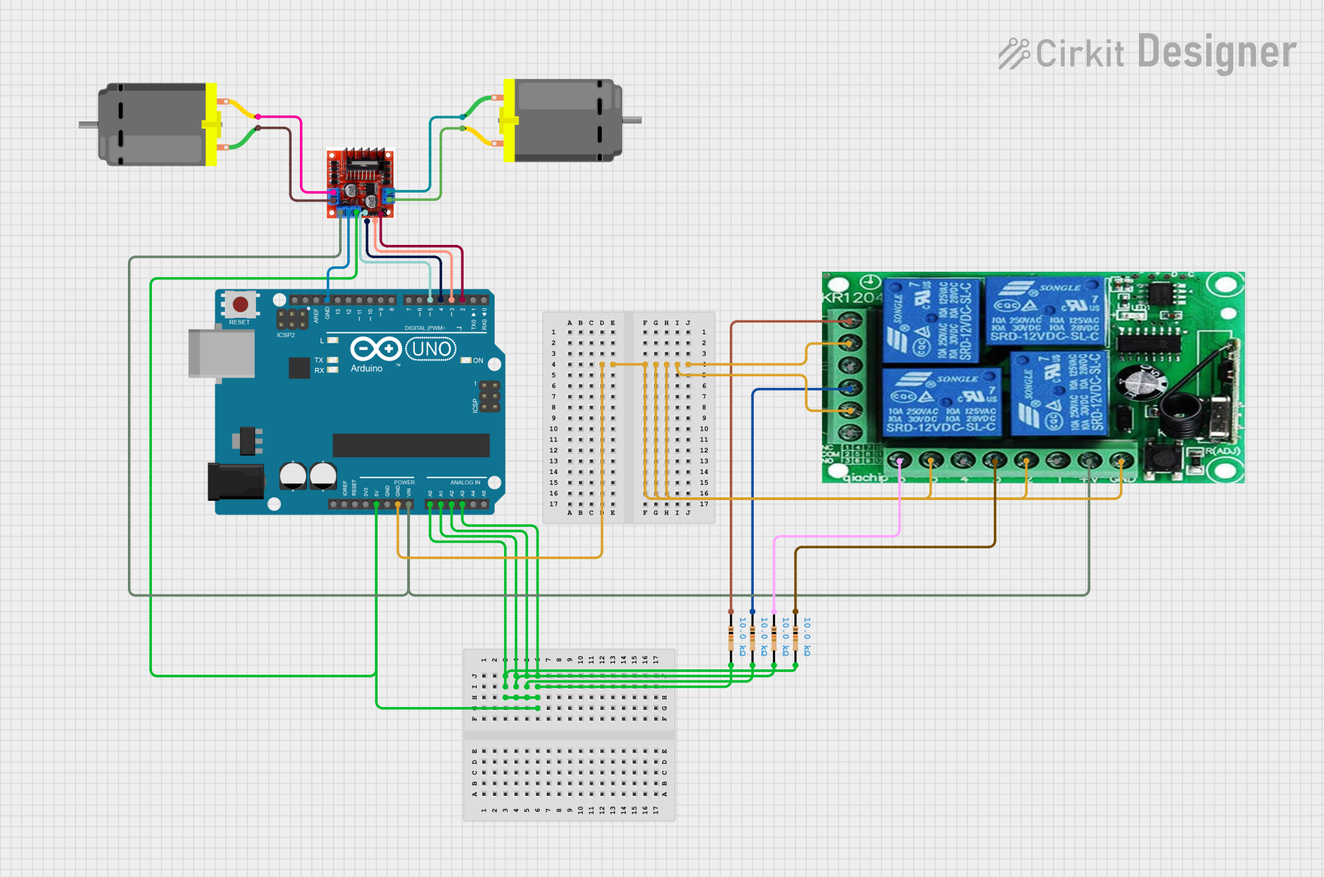
Circuit Documentation
Summary
This circuit is designed to control two DC motors using an Arduino UNO, a 12V 4-channel wireless relay, and a motor driver controller. The motors can be controlled via a remote control with four buttons (A, B, C, D) to perform different actions such as moving both motors, stopping one motor, or stopping both motors.
Component List
Arduino UNO
- Description: A microcontroller board based on the ATmega328P.
- Pins: UNUSED, IOREF, Reset, 3.3V, 5V, GND, Vin, A0, A1, A2, A3, A4, A5, SCL, SDA, AREF, D13, D12, D11, D10, D9, D8, D7, D6, D5, D4, D3, D2, D1, D0
DC Motor
- Description: A simple DC motor.
- Pins: pin 1, pin 2
Wireless Relay 12V 4Ch
- Description: A 12V 4-channel wireless relay module.
- Pins: NO 12, NC 7, COM 8, NO 9, NC 10, COM 11, NO 6, COM 5, NC 4, NO 3, COM 2, NC 1, +V, GND
Resistor (10k Ohms)
- Description: A resistor with a resistance of 10k Ohms.
- Pins: pin1, pin2
L298N Motor Driver Controller Board Module Stepper Motor
- Description: A motor driver module for controlling stepper motors.
- Pins: Output A, +12v Power, +5v Power, Ground, Output B, Input 4, Input 3, Input 2, Input 1
Wiring Details
Arduino UNO
GND is connected to:
- Wireless Relay 12V 4Ch (COM 2, GND, COM 8, COM 11, COM 5)
- L298N Motor Driver Controller Board Module Stepper Motor (Ground)
5V is connected to:
- Resistor (pin2)
- L298N Motor Driver Controller Board Module Stepper Motor (+5v Power)
Vin is connected to:
- Wireless Relay 12V 4Ch (+V)
- L298N Motor Driver Controller Board Module Stepper Motor (+12v Power)
A0 is connected to:
- Resistor (pin2)
A1 is connected to:
- Resistor (pin2)
A2 is connected to:
- Resistor (pin2)
A3 is connected to:
- Resistor (pin2)
D5 is connected to:
- L298N Motor Driver Controller Board Module Stepper Motor (Input 1)
D4 is connected to:
- L298N Motor Driver Controller Board Module Stepper Motor (Input 2)
D3 is connected to:
- L298N Motor Driver Controller Board Module Stepper Motor (Input 3)
D2 is connected to:
- L298N Motor Driver Controller Board Module Stepper Motor (Input 4)
DC Motor
Motor 1:
- pin 1 is connected to L298N Motor Driver Controller Board Module Stepper Motor (Output A)
- pin 2 is connected to L298N Motor Driver Controller Board Module Stepper Motor (Output A)
Motor 2:
- pin 1 is connected to L298N Motor Driver Controller Board Module Stepper Motor (Output B)
- pin 2 is connected to L298N Motor Driver Controller Board Module Stepper Motor (Output B)
Wireless Relay 12V 4Ch
- NO 6 is connected to Resistor (pin1)
- NO 3 is connected to Resistor (pin1)
- NO 9 is connected to Resistor (pin1)
- NO 12 is connected to Resistor (pin1)
Resistor (10k Ohms)
Resistor 1:
- pin1 is connected to Wireless Relay 12V 4Ch (NO 9)
- pin2 is connected to Arduino UNO (A0)
Resistor 2:
- pin1 is connected to Wireless Relay 12V 4Ch (NO 12)
- pin2 is connected to Arduino UNO (A1)
Resistor 3:
- pin1 is connected to Wireless Relay 12V 4Ch (NO 6)
- pin2 is connected to Arduino UNO (A2)
Resistor 4:
- pin1 is connected to Wireless Relay 12V 4Ch (NO 3)
- pin2 is connected to Arduino UNO (A3)
L298N Motor Driver Controller Board Module Stepper Motor
- +12v Power is connected to Arduino UNO (Vin)
- +5v Power is connected to Arduino UNO (5V)
- Ground is connected to Arduino UNO (GND)
- Input 1 is connected to Arduino UNO (D5)
- Input 2 is connected to Arduino UNO (D4)
- Input 3 is connected to Arduino UNO (D3)
- Input 4 is connected to Arduino UNO (D2)
- Output A is connected to:
- DC Motor 1 (pin 1, pin 2)
- Output B is connected to:
- DC Motor 2 (pin 1, pin 2)
Code Documentation
/*
 * This Arduino sketch controls two DC motors using a 12V 4-channel wireless
 * relay and a remote control with four buttons (A, B, C, D). The behavior is
 * as follows:
 * - Button A: Both motors move.
 * - Button B: Only motor 1 moves, motor 2 stops.
 * - Button C: Only motor 2 moves, motor 1 stops.
 * - Button D: Both motors stop.
 */

// Pin definitions
const int motor1Pin1 = 5;
const int motor1Pin2 = 4;
const int motor2Pin1 = 3;
const int motor2Pin2 = 2;
const int relayPinA = A0;
const int relayPinB = A1;
const int relayPinC = A2;
const int relayPinD = A3;

void setup() {
  // Set motor pins as outputs
  pinMode(motor1Pin1, OUTPUT);
  pinMode(motor1Pin2, OUTPUT);
  pinMode(motor2Pin1, OUTPUT);
  pinMode(motor2Pin2, OUTPUT);
  // Set relay pins as inputs
  pinMode(relayPinA, INPUT);
  pinMode(relayPinB, INPUT);
  pinMode(relayPinC, INPUT);
  pinMode(relayPinD, INPUT);
}

void loop() {
  // Read relay states
  bool buttonA = digitalRead(relayPinA);
  bool buttonB = digitalRead(relayPinB);
  bool buttonC = digitalRead(relayPinC);
  bool buttonD = digitalRead(relayPinD);

  // Control motors based on button presses
  if (buttonA) {
    // Both motors move
    digitalWrite(motor1Pin1, HIGH);
    digitalWrite(motor1Pin2, LOW);
    digitalWrite(motor2Pin1, HIGH);
    digitalWrite(motor2Pin2, LOW);
  } else if (buttonB) {
    // Only motor 1 moves
    digitalWrite(motor1Pin1, HIGH);
    digitalWrite(motor1Pin2, LOW);
    digitalWrite(motor2Pin1, LOW);
    digitalWrite(motor2Pin2, LOW);
  } else if (buttonC) {
    // Only motor 2 moves
    digitalWrite(motor1Pin1, LOW);
    digitalWrite(motor1Pin2, LOW);
    digitalWrite(motor2Pin1, HIGH);
    digitalWrite(motor2Pin2, LOW);
  } else if (buttonD) {
    // Both motors stop
    digitalWrite(motor1Pin1, LOW);
    digitalWrite(motor1Pin2, LOW);
    digitalWrite(motor2Pin1, LOW);
    digitalWrite(motor2Pin2, LOW);
  }
}
This code sets up the Arduino to control two DC motors based on the input from a 12V 4-channel wireless relay. The motors are controlled by reading the state of the relay pins and setting the motor pins accordingly.