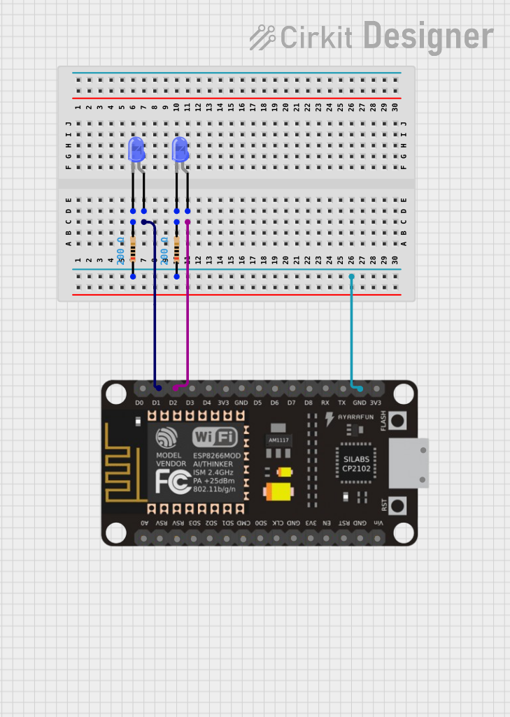
ESP8266-Controlled Dual LED Blinker

Circuit Documentation
Summary of the Circuit
This circuit incorporates an ESP-8266 microcontroller, two resistors, and two LEDs. The ESP-8266 is responsible for controlling the LEDs, which are connected to its digital output pins. Each LED is connected in series with a resistor to limit the current through the LED, ensuring that it operates within its safe parameters. The resistors have the same value, providing uniform current limiting for both LEDs. The ground connections for the LEDs are shared through the resistors, which are then connected to the ground pin of the ESP-8266.
Component List
Resistor
- Description: A passive two-terminal electrical component that implements electrical resistance as a circuit element.
- Purpose: To limit the current flowing through the LEDs, protecting them from excessive current.
- Properties:
- Resistance: 200 Ohms
ESP-8266 Controller
- Description: A low-cost Wi-Fi microchip with full TCP/IP stack and microcontroller capability.
- Purpose: To control the operation of the LEDs, potentially allowing for wireless control if programmed accordingly.
- Pins: A0, RSV, SD3, SD5, SD1, CMD, D0, D1, D2, D3, D4, 3V3, GND, D5, D6, SD0, CLK, RST, EN, D7, D8, RX, TX, Vin, 5V
LED: Two Pin (blue)
- Description: A light-emitting diode that emits blue light when a forward current passes through it.
- Purpose: To provide a visual indication, which could be used for status display, notifications, or other signaling purposes.
- Pins: cathode, anode
Wiring Details
Resistor
- Connections:
- One end connected to the ground (GND) of the ESP-8266 Controller.
- The other end connected to the cathode of an LED.
ESP-8266 Controller
- Connections:
- Pin D1 connected to the anode of one LED.
- Pin D2 connected to the anode of the other LED.
- GND pin connected to one end of both resistors.
LED: Two Pin (blue)
- Connections:
- Anode connected to a digital output pin (D1 or D2) of the ESP-8266 Controller.
- Cathode connected to one end of a resistor, which is then connected to the ground (GND) of the ESP-8266 Controller.
Documented Code
No code has been provided for the microcontroller. To control the LEDs, code should be written and uploaded to the ESP-8266. The code would typically initialize the digital pins D1 and D2 as outputs and then toggle them to turn the LEDs on or off. Without the code, the functionality of the circuit cannot be fully described.