
Arduino Mega 2560 Controlled Multi-Stepper Motor System with Servo Integration
View and Edit Project In Cirkit Designer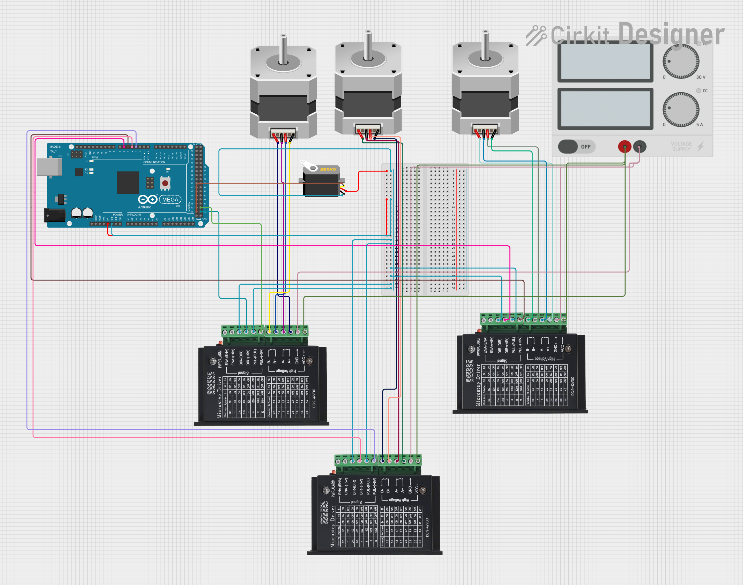
Circuit Documentation
Summary
This circuit involves an Arduino Mega 2560 microcontroller, three TB6600 Micro Stepping Motor Drivers, three Bipolar Stepper Motors, a Servo, and a Power Supply. The Arduino Mega 2560 controls the stepper motors and the servo, while the TB6600 drivers interface between the Arduino and the stepper motors. The power supply provides the necessary voltage and current to the TB6600 drivers.
Component List
Arduino Mega 2560
- Description: A microcontroller board based on the ATmega2560.
- Pins: IOREF, RESET, 3V3, 5V, GND, VIN, A0-A15, D0-D53, AREF, SDA, SCL
TB6600 Micro Stepping Motor Driver
- Description: A driver for controlling bipolar stepper motors.
- Pins: ENA-, ENA+, DIR-, DIR+, PUL-, PUL+, B-, B+, A-, A+, GND, VCC
Stepper Motor (Bipolar)
- Description: A bipolar stepper motor with four pins.
- Pins: D, B, C, A
Servo
- Description: A servo motor with three pins.
- Pins: gnd, vcc, pulse
Power Supply
- Description: A power supply unit.
- Pins: +, -
Wiring Details
Arduino Mega 2560
- 5V connected to vcc of Servo
- GND connected to gnd of Servo, DIR- and PUL- of all TB6600 drivers
- D3 PWM connected to PUL+ of TB6600 driver 1
- D4 PWM connected to DIR+ of TB6600 driver 1
- D5 PWM connected to PUL+ of TB6600 driver 2
- D6 PWM connected to DIR+ of TB6600 driver 2
- D52 connected to pulse of Servo
- D53 connected to DIR+ of TB6600 driver 3
- D51 connected to PUL+ of TB6600 driver 3
TB6600 Micro Stepping Motor Driver 1
- DIR- connected to GND of Arduino
- PUL- connected to GND of Arduino
- PUL+ connected to D3 PWM of Arduino
- DIR+ connected to D4 PWM of Arduino
- B- connected to D of Stepper Motor 1
- B+ connected to B of Stepper Motor 1
- A- connected to C of Stepper Motor 1
- A+ connected to A of Stepper Motor 1
- GND connected to - of Power Supply
- VCC connected to + of Power Supply
TB6600 Micro Stepping Motor Driver 2
- DIR- connected to GND of Arduino
- PUL- connected to GND of Arduino
- PUL+ connected to D5 PWM of Arduino
- DIR+ connected to D6 PWM of Arduino
- B- connected to D of Stepper Motor 2
- B+ connected to B of Stepper Motor 2
- A- connected to C of Stepper Motor 2
- A+ connected to A of Stepper Motor 2
- GND connected to - of Power Supply
- VCC connected to + of Power Supply
TB6600 Micro Stepping Motor Driver 3
- DIR- connected to GND of Arduino
- PUL- connected to GND of Arduino
- PUL+ connected to D51 of Arduino
- DIR+ connected to D53 of Arduino
- B- connected to D of Stepper Motor 3
- B+ connected to B of Stepper Motor 3
- A- connected to C of Stepper Motor 3
- A+ connected to A of Stepper Motor 3
- GND connected to - of Power Supply
- VCC connected to + of Power Supply
Stepper Motor 1
- D connected to B- of TB6600 driver 1
- B connected to B+ of TB6600 driver 1
- C connected to A- of TB6600 driver 1
- A connected to A+ of TB6600 driver 1
Stepper Motor 2
- D connected to B- of TB6600 driver 2
- B connected to B+ of TB6600 driver 2
- C connected to A- of TB6600 driver 2
- A connected to A+ of TB6600 driver 2
Stepper Motor 3
- D connected to B- of TB6600 driver 3
- B connected to B+ of TB6600 driver 3
- C connected to A- of TB6600 driver 3
- A connected to A+ of TB6600 driver 3
Servo
- vcc connected to 5V of Arduino
- gnd connected to GND of Arduino
- pulse connected to D52 of Arduino
Power Supply
- + connected to VCC of all TB6600 drivers
- - connected to GND of all TB6600 drivers
Documented Code
Arduino Mega 2560 Code
void setup() {
  // put your setup code here, to run once:

}

void loop() {
  // put your main code here, to run repeatedly:

}
Additional Documentation
// No additional documentation provided.